英语
英语 俄语
俄语Content
- 1 How to Assemble a Cam Lock: The Short Answer First
- 2 What Is a Camlock Coupling and How Does It Work
- 3 What You Need Before You Start Assembly
- 4 Step-by-Step: How to Assemble a Cam Lock Coupling
- 5 How to Disconnect a Camlock Coupling Safely
- 6 Camlock Coupling Assembly by Material Type
- 7 Common Assembly Mistakes and How to Avoid Them
- 8 How to Attach a Camlock Coupling to a Hose
- 9 Pressure Ratings and Size Selection for Camlock Couplings
- 10 Maintaining Camlock Couplings for Long Service Life
- 11 Industry-Specific Camlock Coupling Assembly Considerations
- 12 Troubleshooting: Why Your Camlock Coupling Is Leaking
How to Assemble a Cam Lock: The Short Answer First
To assemble a camlock coupling, insert the male adapter (Part B) into the female coupler (Part A), align the cam arms over the grooves on the adapter, and press both cam arms down simultaneously until they lock into place with a firm click. That's it. No tools required. The entire connection takes under five seconds when you know what you're doing.
But there's a lot that separates a correct assembly from a dangerous one. The wrong size, a worn cam arm, a missing dust cap, or mismatched materials can turn a simple coupling into a leak, a spill, or a pressure failure mid-transfer. This guide covers every step in detail — including what to check before you connect, how to identify bad couplings, and how different cam lock types are assembled differently.
What Is a Camlock Coupling and How Does It Work
A camlock coupling — also called a cam and groove coupling — is a type of hose fitting designed for fast, tool-free connection and disconnection of fluid transfer lines. They're used across agriculture, petroleum, chemical processing, food and beverage, military fueling, and fire suppression industries. The design is standardized under MIL-C-27487 (military) and ANSI/ASME B16.17, which means parts from different manufacturers are interchangeable as long as they share the same size and type designation.
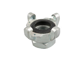
The coupling works through a cam-and-groove locking mechanism. The female coupler holds two pivoting arms (the "cams") on either side of its body. The male adapter has a groove machined around its circumference near the end. When the male adapter is inserted into the female coupler, the cam arms swing down into the groove and lock the two pieces together, compressing a gasket inside the female coupler to form a leak-free seal.
The system is rated for continuous use in sizes ranging from ½ inch to 6 inches in diameter, and pressure ratings vary significantly by material — from as low as 75 PSI for large-diameter aluminum couplings to over 250 PSI for stainless steel units in smaller sizes.
The Seven Standard Camlock Coupling Types
Camlock couplings are manufactured in seven standard configurations. Understanding which type you're working with is essential before assembly:
| Type | Description | Common Use |
|---|---|---|
| Type A | Female coupler × male NPT thread | Connecting to pipe threads |
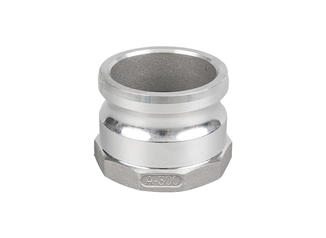
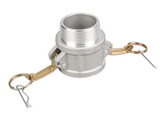
| Type B | Male adapter × female NPT thread | Most common adapter type |
| Type C | Female coupler × hose barb (male end) | Hose-to-coupler connections |
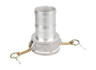
| Type D | Female coupler × hose barb (female end) | High-volume liquid transfer |
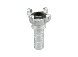
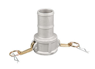
| Type E | Male adapter × hose barb (male end) | Hose-to-adapter connections |
| Type F | Male adapter × male NPT thread | Male-to-male connections |
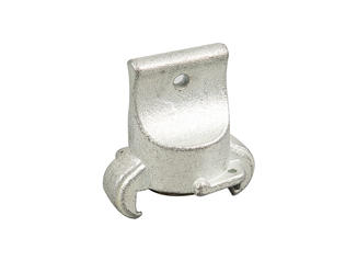
| Type DC | Dust cap (female) | Sealing unused female ends |
What You Need Before You Start Assembly
Before touching any cam lock, confirm the following. Skipping this pre-assembly check is where most leaks and failures start.
Matching Sizes
The male adapter and female coupler must be the same nominal size. A 2-inch adapter will not properly lock into a 2.5-inch coupler even if it physically slides in — the groove won't line up with the cam arms, and the gasket won't seat. Sizes are typically stamped on the body of the coupling. If the marking is worn off, measure the inner diameter of the female coupler and compare it to the outer diameter of the male adapter's groove section.
Compatible Materials
Camlock couplings are made from aluminum, stainless steel (304 and 316), brass, polypropylene, and nylon. The material matters because of galvanic corrosion risk and chemical compatibility. Connecting aluminum to stainless steel in a saltwater or chemical environment will accelerate corrosion at the joint. For food-grade applications, only stainless steel or polypropylene couplings should be used. For petroleum products, aluminum is common. For strong acids, PTFE-lined or polypropylene units are standard.
Gasket Condition
The gasket sits inside the female coupler and is the only sealing element in the entire assembly. If it's cracked, deformed, missing, or chemically incompatible with your fluid, you don't have a seal — you have a leak waiting to happen. Standard gaskets are EPDM (for water, steam, mild chemicals), Buna-N / Nitrile (for petroleum and oils), Viton (for aggressive chemicals), and silicone (for food-grade and high-temperature use). Always inspect the gasket before connecting. Replace any gasket that shows surface cracking, swelling, or hardening.
Cam Arm Integrity
Open both cam arms fully and look at the inside surface of each arm where it contacts the groove. This contact point should be smooth and free of heavy pitting or deformation. Cam arms that are bent outward, cracked at the pivot, or loose on their pins will not hold pressure reliably. A quick test: with no adapter inserted, close the cam arms fully. They should snap to a closed position with firm resistance and not spring back open on their own.
Step-by-Step: How to Assemble a Cam Lock Coupling
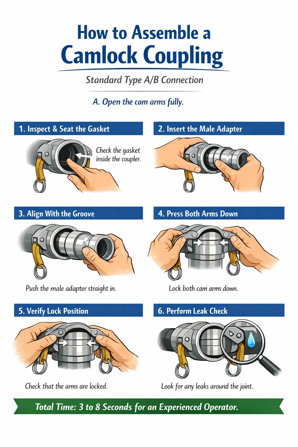
The following steps apply to the standard Type A/B connection — a female coupler receiving a male adapter — which is by far the most common assembly scenario in the field.
- Open the cam arms fully. Pull both cam arms outward until they are horizontal or slightly past horizontal. They should move freely without requiring excessive force. If an arm is stiff, inspect the pivot pin for corrosion or debris and clean before continuing.
- Inspect and seat the gasket. Look inside the female coupler. The gasket should be flush against the internal shoulder of the coupler — not twisted, folded, or protruding unevenly. Press it firmly into its seat if it has shifted. If the gasket is missing, stop and install the correct replacement before proceeding.
- Insert the male adapter straight in. Hold the male adapter (Part B) and push it directly into the open end of the female coupler. Insert it fully until the adapter's face contacts the gasket. Do not insert it at an angle — angled insertion can dislodge the gasket and create an uneven seat.
- Align the cam arms over the groove. With the adapter fully inserted, the machined groove around the adapter's circumference should be lined up directly beneath the cam arms. If the groove is not visible or the adapter is not fully seated, do not attempt to close the arms.
- Close both cam arms simultaneously. Using both hands, press the cam arms downward at the same time. Apply even pressure on both sides. As each arm rotates down, its cam surface engages the groove on the adapter and begins to pull the two pieces together, compressing the gasket. Continue pressing until both arms click into or past their over-center locking point.
- Verify the locked position. Once closed, the cam arms should sit flush or slightly angled toward the body of the coupler. Try to pull the adapter out — it should not move. Try to push the cam arms open with your thumb — they should resist and require deliberate force to open. If either arm opens easily under light pressure, the coupling is not properly locked.
- Perform a low-pressure leak check before full operation. If possible, open the fluid source slowly and check around the coupler body and the cam arm hinges for any seeping. A properly assembled camlock coupling with a good gasket will show zero weeping at the joint.
Total assembly time for an experienced operator: 3 to 8 seconds. For someone assembling for the first time, allow 30 to 60 seconds to confirm each step before moving to the next.
How to Disconnect a Camlock Coupling Safely
Disconnection is simpler than assembly but carries more risk if fluid is still present in the line. Never disconnect a camlock coupling under pressure. This is the single most important safety rule for any cam and groove system.
- Shut off the fluid source completely.
- Relieve residual pressure in the line — open a downstream valve or allow the system to bleed down to zero PSI.
- Grip both cam arms and pull them outward and upward simultaneously. They should rotate back past their lock point and release the adapter.
- Pull the male adapter straight out. Residual fluid may drain — point the adapter downward into a collection container if this is a concern.
- Immediately install dust caps on both the male adapter and female coupler to prevent contamination and protect the gasket.
If the cam arms are difficult to open, do not use a pry bar directly on the arm — this can bend or crack it. Instead, use a rubber mallet to gently tap the arm upward from the underside, or apply a penetrating lubricant to the pivot pin and wait before retrying.
Camlock Coupling Assembly by Material Type
The assembly process is the same mechanically for all camlock materials, but the handling requirements differ. Here's what changes based on material:
Aluminum Camlock Couplings
Aluminum is the most widely used camlock material due to its light weight and low cost. It handles petroleum products, water, and many agricultural chemicals well. However, aluminum is susceptible to galling — a form of adhesive wear that happens when two aluminum surfaces slide against each other under pressure. To prevent galling during assembly, apply a thin film of anti-seize compound to the male adapter's seating surface before insertion. Never use steel tools to force aluminum cam arms — this creates burrs that accelerate wear.
Stainless Steel Camlock Couplings
Stainless steel (most commonly 316 SS for chemical and food-grade applications) is harder and more corrosion-resistant than aluminum. It's also heavier and more expensive. The cam arms on stainless units require more force to close than aluminum equivalents of the same size, particularly on 3-inch and larger couplings. This is normal — the tighter tolerances machined into stainless couplings are intentional. On stainless units used in food processing, ensure gaskets are FDA-approved silicone and that the mating surfaces are free of any oil or grease before connection.
Polypropylene Camlock Couplings
Polypropylene cam locks are used for acids, caustics, and chemical transfer applications where metal couplings would corrode. They are significantly lighter than metal but also more brittle, especially at low temperatures. When assembling polypropylene cam locks in ambient temperatures below 40°F (4°C), warm the coupler slightly before assembly — cold polypropylene becomes brittle and the cam arms can crack under the stress of locking. Pressure ratings for polypropylene couplings are typically 25–40% lower than equivalent aluminum units, so verify the rating before use in high-pressure systems.
Brass Camlock Couplings
Brass cam locks are common in compressed air, propane, and natural gas applications. Assembly is identical to aluminum, but brass is heavier and the surfaces can be slippery when oily. Ensure a firm grip when closing cam arms on brass units. Do not use brass couplings with acetylene or ammonia — both react with brass alloys and create dangerous compounds.
Common Assembly Mistakes and How to Avoid Them
Closing One Cam Arm Before the Other
When you close one cam arm first, it pulls the adapter to one side, creating an uneven load on the gasket. The second arm then has to overcome this misalignment to close fully. The result is either a partially engaged second arm or a gasket that's been deformed unevenly. Always close both arms at the same time, applying equal pressure on both sides.
Inserting the Adapter Before Opening the Cam Arms
If the cam arms are closed when you try to push the adapter in, you're forcing the adapter against resistance. Some operators do this and then force the arms open while the adapter is partially in — this can displace the gasket or stress the cam arm pivot pins. Open the arms first, every time.
Using a Mismatched Gasket
A common field fix when the correct gasket isn't available is to use whatever gasket is on hand. This creates chemical compatibility failures that aren't immediately visible. For example, a Buna-N gasket exposed to ketones or strong acids will swell within hours and either blow out or create a deformed seal. A Viton gasket in a steam line above 400°F (204°C) will harden and crack. Always use the correct gasket material for the fluid and temperature range.
Not Checking for the Over-Center Lock
Camlock couplings use an over-center mechanism — the cam arm must rotate slightly past the point of maximum tension to reach its locked position. Operators who stop closing the arm the moment they feel resistance often leave the arm just before the lock point. At this position, line vibration or a light bump can pop the arm open. Push each arm all the way until you feel it drop into the locked position or hear a slight click.
Ignoring Wear on the Cam Groove Contact Surface
The inside of each cam arm has a curved contact surface that rides in the groove of the adapter. Over thousands of connections, this surface wears down. A worn cam arm will still close and appear locked, but it won't generate sufficient clamping force to maintain a seal under pressure fluctuations. If you can close the cam arm with one finger using minimal effort, the cam arm has worn past its useful life. Replace it.
Connecting Under Pressure
Attempting to connect or disconnect a camlock coupling while there is pressure in the line is extremely hazardous. Even a small amount of residual pressure — as little as 10 to 15 PSI — can cause the adapter to eject from the coupler when the cam arms are released, potentially causing serious injury or a hazardous spill. Always confirm zero pressure before any disconnection.
How to Attach a Camlock Coupling to a Hose
Connecting a cam lock to a hose (Type C, D, or E configurations) requires a few additional steps beyond just the cam lock assembly itself. This is where many users make mistakes that compromise both the coupling and the hose.
Hose Barb Connection Method
- Select a camlock with a hose barb end that matches your hose's inner diameter (ID). A 2-inch hose requires a 2-inch barb. The barb should fit snugly — if the hose slides onto the barb without resistance, the ID is too large.
- For rubber hoses, softening the hose end in hot water (around 160°F / 70°C) for 30 seconds makes it easier to push over the barb without damaging the hose wall.
- Push the hose end fully over the barb until it reaches the shoulder of the coupler body. The hose should be seated past at least two full barb ridges.
- Apply a hose clamp or ferrule crimp over the hose where it covers the barb section. For low-pressure applications (under 50 PSI), a single worm-drive clamp is acceptable. For higher pressures, use double clamps or crimp ferrules.
- Tighten the clamp to the hose manufacturer's specified torque. Over-tightening cuts into the hose; under-tightening allows the hose to blow off under pressure.
NPT Threaded Connection Method
For Type A, B, and F couplings that thread onto pipe or fittings:
- Clean the pipe threads with a wire brush to remove scale, rust, or old sealant.
- Apply PTFE tape (2–3 wraps) or thread sealant to the male NPT threads. Wrap the tape in the direction of the thread — clockwise when looking at the thread end.
- Thread the camlock coupling onto the pipe by hand until it's finger-tight, then use a pipe wrench to turn it an additional 1.5 to 2 full turns. Do not over-tighten — NPT threads seal by wedging, and over-tightening cracks the fitting body, particularly on aluminum and polypropylene.
- Orient the cam arm side of the coupler so it's accessible for connection and disconnection during operation.
Pressure Ratings and Size Selection for Camlock Couplings
Choosing the wrong size or pressure rating for a camlock coupling is a safety issue, not just a performance issue. The following table shows typical working pressure ratings for standard camlock coupling sizes across materials:
| Size (inches) | Aluminum (PSI) | Stainless 316 (PSI) | Polypropylene (PSI) | Brass (PSI) |
|---|---|---|---|---|
| ½" | 250 | 250 | 150 | 250 |
| 1" | 200 | 250 | 125 | 200 |
| 1½" | 150 | 200 | 100 | 150 |
| 2" | 125 | 175 | 75 | 125 |
| 3" | 100 | 150 | 50 | 100 |
| 4" | 75 | 125 | 40 | 75 |
| 6" | 75 | 100 | 30 | 75 |
Note that as coupling size increases, working pressure decreases. A 6-inch aluminum camlock coupling rated at 75 PSI is handling the same fluid force as a much larger surface area, which is why larger couplings require lower operating pressures. Always size your coupling to the system's maximum operating pressure, not its average operating pressure.
Maintaining Camlock Couplings for Long Service Life
A well-maintained camlock coupling can last for decades. Neglected ones fail within months. Maintenance is straightforward and takes less than two minutes per coupling.
After Every Use
- Flush the coupler and adapter with clean water if they've been used with chemicals, food products, or petroleum that leaves residue.
- Install dust caps on all open ends. A camlock coupling left uncapped in a dusty environment will accumulate debris in the gasket groove, which becomes an abrasive that damages gaskets during the next connection.
- Close the cam arms on the female coupler when not in use to protect the gasket from UV light (UV degrades most rubber gasket materials).
Monthly Inspection Points
- Gasket: Remove and inspect the gasket. Look for cracks, surface hardening, swelling, or deformation. EPDM and Buna-N gaskets in regular service should be replaced annually as a baseline, regardless of visual condition.
- Cam arm pivot pins: Check for corrosion at the pivot pin. Apply a drop of light oil (for metal couplings) or silicone lubricant (for polypropylene) to each pin if the arm movement is stiff.
- Cam arm contact surface: Look at the inside curve of each arm for heavy wear, gouging, or polishing that has reduced the surface's depth.
- Adapter groove: Check the groove on the male adapter for rounding or chipping. A degraded groove will cause the cam arms to not seat fully.
- Body condition: On aluminum couplings, look for deep pitting from corrosion. On polypropylene, look for stress cracking around the cam arm mounting points.
When to Replace vs. Repair
Individual gaskets and sometimes cam arms can be replaced without replacing the entire coupling. Cam arm replacement kits are available from most camlock manufacturers and typically cost $3 to $15 per arm depending on size and material. However, if the coupler body has been cracked, deeply corroded, or bent, replace the entire unit. A failed coupling body under pressure can cause ejection of the adapter — a genuine life-safety hazard. The cost of replacing a $25 coupling is always lower than the cost of a fluid spill, a chemical exposure incident, or a pressure ejection injury.
Industry-Specific Camlock Coupling Assembly Considerations
Agriculture and Chemical Tank Transfer
Agricultural camlock applications typically involve fertilizers, herbicides, and pesticides — all of which are chemically aggressive to standard gasket materials. Viton gaskets are standard in these environments. Assembly in the field often happens quickly, in poor lighting, and by operators wearing gloves — conditions where misassembly is more likely. In agricultural settings, a simple color-coding system for different chemical lines (e.g., red arms for herbicides, blue for fertilizer) reduces misconnection incidents significantly.
Petroleum and Fuel Transfer
Petroleum camlock applications require Buna-N or Viton gaskets and aluminum or stainless steel bodies. Static electricity is a significant hazard during fuel transfer — an ungrounded coupling can generate a spark that ignites fuel vapors. In petroleum applications, camlock couplings used with flammable liquids should always be used with a bonding wire clipped between the receiving container and the supply line, and both systems should be grounded before connection. Some specialized petroleum camlocks include a built-in grounding lug for this purpose.
Food and Beverage Processing
Food-grade camlock assembly has strict requirements beyond the mechanical steps. All couplings must be cleaned and sanitized before and after each use — typically with a CIP (Clean-in-Place) caustic wash followed by an acid rinse and a hot water flush. Gaskets must be FDA-compliant silicone or EPDM. No petroleum-based lubricants can be used on any food-contact surface — use food-grade silicone grease only. After disassembly in food applications, the gasket must be removed, cleaned separately, and inspected for any embedded particulates before reinstallation.
Fire Suppression and Water Transfer
Camlock couplings are used in portable pump systems, tank-to-tank water transfer, and irrigation. In fire suppression applications, assembly speed matters more than in any other context. Operators should practice assembly until the motion is automatic — in smoke and low visibility, the physical feel of the cam arms locking must be reliable without visual confirmation. Large-diameter couplings (4-inch and 6-inch) used in high-volume water transfer may require two operators to align and connect safely due to the weight of filled hoses.
Troubleshooting: Why Your Camlock Coupling Is Leaking
If a properly assembled camlock coupling is leaking, the cause falls into one of these categories:
- Leaking from the face of the connection (between adapter and coupler): The gasket is damaged, missing, incompatible with the fluid, or has been displaced during assembly. Disconnect, inspect, and replace the gasket.
- Leaking from around the cam arms: The cam arms are not fully locked into the over-center position. Disconnect completely and reconnect, ensuring both arms are pressed fully closed.
- Leaking from the coupler body itself: The coupling has a crack or corrosion hole in the body. Remove from service immediately and replace.
- Weeping at the NPT thread connection: The thread sealant has failed or was applied incorrectly. Disconnect, clean the threads, and reapply PTFE tape or thread sealant.
- Slow leak that appears only under pressure: The cam arms are worn and not generating sufficient clamping force to compress the gasket adequately at operating pressure. Replace the cam arms or the entire coupling.
- Leak that appears only after multiple thermal cycles: The gasket material is not compatible with the temperature range and is hardening or swelling with temperature changes. Switch to a gasket material rated for the full temperature range of the application.