英语
英语 俄语
俄语Content
- 1 How to Install a Cam Lock: The Short Answer
- 2 Understanding Camlock Coupling Types Before You Install
- 3 Tools and Materials You Need Before Starting
- 4 Step-by-Step: How to Install a Camlock Coupling on a Hose
- 5 Step-by-Step: How to Install a Camlock Coupling on Threaded Pipe
- 6 How to Install a Cam Lock on Furniture (Flat-Pack Assembly)
- 7 Gasket Selection for Camlock Couplings: Why It Matters More Than You Think
- 8 Pressure Ratings and What Happens When You Exceed Them
- 9 Common Mistakes During Camlock Coupling Installation
- 10 Safety Considerations When Working with Camlock Coupling Systems
- 11 Maintenance Practices That Extend Camlock Coupling Life
- 12 Choosing the Right Camlock Coupling for Your Application
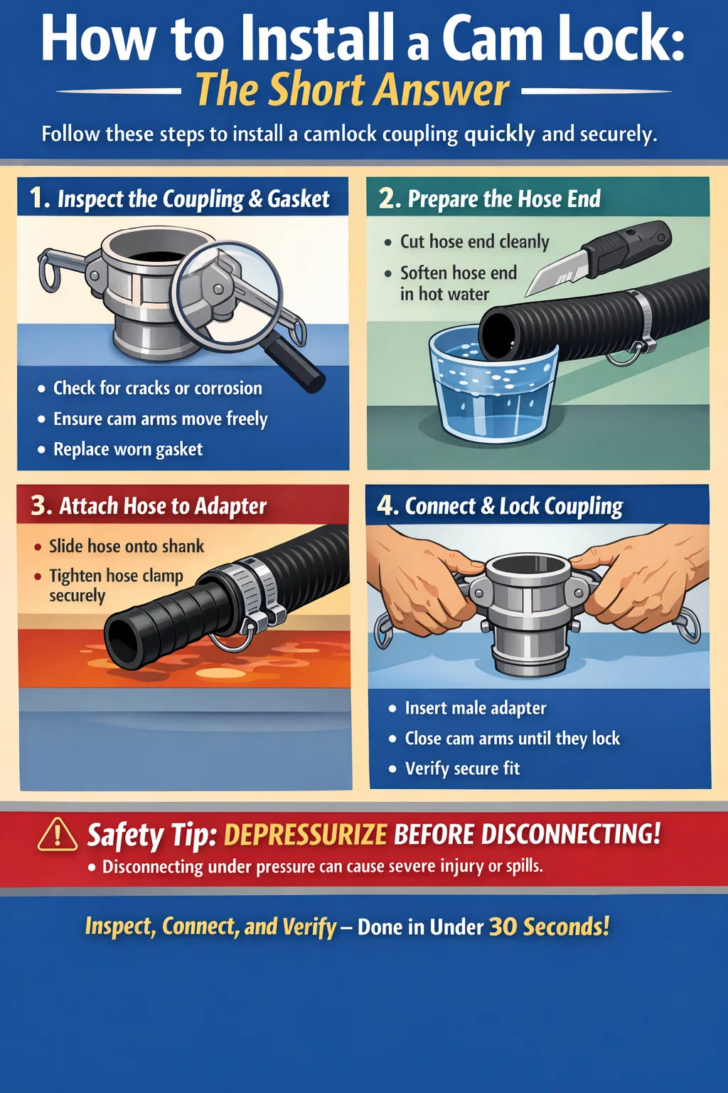
How to Install a Cam Lock: The Short Answer
Installing a cam lock — whether it is a furniture cam lock or a camlock coupling used in fluid transfer applications — follows a straightforward sequence: identify the correct size and type, prepare the mounting surface or pipe end, insert the fitting, and secure it by rotating the cam arms until they lock firmly in place. For camlock couplings specifically, no tools are required for connection, which is precisely why they are used across agriculture, petroleum, chemical processing, and food manufacturing industries worldwide. The entire connection process typically takes under 30 seconds once you are familiar with the system.
That said, doing it correctly matters. A poorly installed cam lock can lead to leaks, pressure failures, or in fluid systems, catastrophic spills. This guide walks through everything you need to know — from understanding the different camlock coupling types to step-by-step installation, common mistakes, and maintenance practices that extend service life.
Understanding Camlock Coupling Types Before You Install
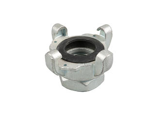
Before any installation begins, you need to know which type of camlock coupling you are working with. The industry follows the MIL-C-27487 standard (now largely superseded by the commercial equivalent), which defines seven standard configurations, each designated by a letter. Choosing the wrong type is one of the most common reasons installations fail or leak.
| Type | Description | Male/Female | Common Use |
|---|---|---|---|
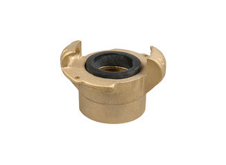
| Type A | Female coupler × male NPT thread | Female | Connecting to threaded male pipe fittings |
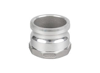
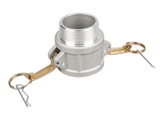
| Type B | Male adapter × female NPT thread | Male | Attaching to female threaded outlets |
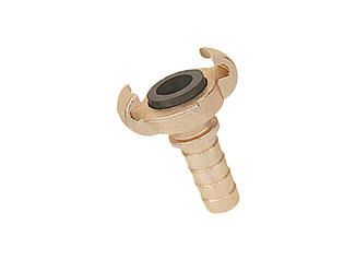
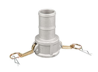
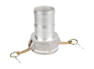
| Type C | Female coupler × hose shank | Female | Hose-to-coupling connections |
| Type D | Female coupler × female NPT thread | Female | Pipe connections with female threads |
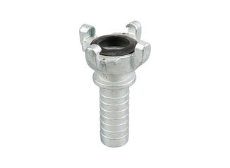
| Type E | Male adapter × hose shank | Male | Hose-end male adapter |
| Type F | Male adapter × male NPT thread | Male | Tank outlets and pump connections |
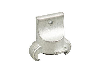
| Type DC | Dust cap (female coupler) | Cap | Sealing unused female ends |
Camlock couplings are available in sizes ranging from 1/2 inch to 6 inches in diameter, with 2-inch and 3-inch sizes being the most common in agricultural and industrial settings. Always match the coupling size to your hose or pipe inner diameter — using a 2-inch coupling on a 1.5-inch hose shank is a mistake that will cause leaks under pressure.
Material selection also plays a major role. The most common materials include:
- Aluminum: Lightweight and cost-effective, widely used in agriculture and water transfer. Not suitable for chlorinated chemicals or seawater.
- Stainless steel (304 or 316): Corrosion-resistant, ideal for food-grade applications and chemical handling. 316 grade handles chlorides better.
- Polypropylene: Excellent chemical resistance, used in fertilizers and mild acids. Rated for lower pressures than metal versions.
- Brass: Common in fuel transfer and petroleum applications. Not compatible with acetylene or ammonia.
- Nylon: Lightweight alternative for low-pressure, non-chemical applications.
Matching material to the fluid being transferred is non-negotiable. For example, using an aluminum camlock coupling with sodium hypochlorite (bleach) will cause rapid corrosion and structural failure, creating a serious safety hazard.
Tools and Materials You Need Before Starting
One of the major advantages of camlock coupling systems is that the coupling-to-coupling connection itself requires no tools. However, preparing the hose end or threaded pipe connection does require some basic equipment. Here is what you should have on hand before you start:
- The correct camlock coupling type and size for your application
- Replacement gaskets (EPDM, Buna-N, or silicone depending on fluid type)
- Hose clamps and a flathead or Torx screwdriver, if connecting to a hose
- PTFE thread tape (also called Teflon tape), for threaded connections
- Pipe wrench or adjustable wrench for NPT threaded ends
- Clean cloth or rag for wiping coupling ends
- Appropriate personal protective equipment (PPE) based on fluid type — gloves, goggles, and chemical-resistant clothing if dealing with hazardous materials
For furniture cam locks (the kind used in flat-pack furniture like drawer assemblies or cabinet connections), you will need a drill with the correct bit size — typically a 15mm Forstner bit for the cam housing hole and a 5mm or 6mm bit for the bolt hole — plus a screwdriver or Allen key depending on the bolt type.
Step-by-Step: How to Install a Camlock Coupling on a Hose
This is the most common installation scenario — attaching a camlock coupling to a flexible hose, such as when setting up irrigation systems, pump connections, or liquid transfer rigs. Follow these steps carefully.
Step 1: Inspect the Coupling and Gasket
Before anything else, examine the camlock coupling body for cracks, deformation, or corrosion. Check that the cam arms move freely and snap into place without excessive play. Look inside the female coupler — the groove where the gasket sits should be clean and free of debris. If the gasket looks compressed, cracked, hardened, or misshapen, replace it immediately. A worn gasket is the number one cause of camlock coupling leaks. Gaskets cost almost nothing compared to the cost of a fluid spill or system shutdown.
Step 2: Prepare the Hose End
Cut the hose squarely and cleanly using a hose cutter or sharp utility knife. A diagonal or ragged cut makes it difficult to push the hose onto the shank fully and creates uneven stress on the hose clamps. Soften the end of rubber or PVC hose by dipping it in hot water for 30 to 60 seconds — this makes it much easier to push over the hose shank without tearing or kinking.
Step 3: Attach the Hose to the Shank
Push the hose over the hose shank of the camlock adapter (Type C or Type E). The hose should slide over all the ridges on the shank. Most shank designs have two to four raised rings or barbs — the hose end should pass all of them. If the hose stops short of the coupling collar, the clamp will not be positioned correctly and you risk the hose pulling off under pressure.
Position your hose clamp over the hose, approximately 10mm to 15mm from the end of the hose (not right at the edge). Tighten the clamp until it is firm — typically around 40 to 60 inch-pounds of torque for standard worm-drive clamps on a 2-inch hose. For higher-pressure applications, use two clamps spaced about 15mm apart for redundancy.
Step 4: Connect the Male Adapter to the Female Coupler
Open the cam arms on the female coupler by pulling them outward and back. Insert the male adapter into the female coupler mouth. You should feel or hear the adapter seat fully — there should be no gap between the two coupling faces. Once seated, push the cam arms forward and down simultaneously until they click or snap into their locked position. The arms should sit flat against the body of the female coupler. If one arm does not close fully, the adapter may not be fully inserted — remove and reseat it before trying again.
Step 5: Verify the Connection Before Pressurizing
Try to pull the two halves apart by hand. A correctly installed camlock coupling will not separate under hand force alone. Visually inspect the cam arm positions — both should be fully closed and parallel to the body, not at an angle. Give each arm a firm press to confirm it is locked, not just resting in a closed-looking position. Once you are confident the connection is secure, slowly open any valves and bring the system up to operating pressure. Watch the coupling area for any signs of seeping or misting, which would indicate a gasket issue or incomplete engagement.
Step-by-Step: How to Install a Camlock Coupling on Threaded Pipe
When you need to add a camlock coupling to an existing threaded pipe system — such as a pump outlet, tank drain, or manifold — the process involves the Type A, B, D, or F adapter depending on your configuration.
Applying Thread Tape Correctly
Wrap PTFE tape clockwise around the male NPT threads — meaning you wrap in the same direction the coupling will be tightened. Apply two to three wraps for standard connections, four to five wraps for finer threads or applications with higher vibration. Start at the first thread and work toward the end, stretching the tape slightly as you go so it seats into the thread grooves. Do not wrap over the first thread — leaving it exposed helps start the threading process cleanly.
Threading and Tightening
Start threading by hand to ensure you are not cross-threading. NPT threads are tapered, so they should feel progressively tighter as you thread in. Hand-tighten until snug, then use a pipe wrench for the final tightening. For typical 2-inch aluminum camlock fittings, tighten two to three turns past hand-tight. Over-tightening can crack aluminum bodies or damage threads — if you feel significant resistance before two turns past hand-tight, stop and check for cross-threading or thread damage.
Once the threaded end is secure, connect the cam coupling end following the same process described in the hose section above — open cam arms, insert adapter, close and lock the arms, then verify before pressurizing.
How to Install a Cam Lock on Furniture (Flat-Pack Assembly)
Furniture cam locks — also called cam bolts or confirmat fittings — are completely different from camlock couplings. They are used to join panels in flat-pack furniture, such as drawer boxes, wardrobe carcasses, cabinet sides, and bed frames. Understanding how to install them correctly prevents wobbling joints and stripped holes.
Drilling the Cam Housing Hole
The cam housing sits in a circular recess drilled into the face of one panel. The standard cam lock diameter is 15mm, and the hole depth is typically 12.5mm. Use a Forstner bit rather than a spade bit — Forstner bits produce a flat-bottomed hole with clean edges, which is important because the cam housing needs to sit flush and level. Mark your hole center precisely using the manufacturer's hardware template if provided, or measure from the panel edge — typically 34mm from the nearest edge for standard furniture hardware.
Drilling the Bolt Hole
The cam bolt (a short cylindrical bolt with a notched or hooked head) is inserted into the edge of the adjoining panel. The bolt hole diameter is typically 5mm or 6mm, drilled to a depth of 13mm to 15mm depending on the bolt length. The critical factor here is alignment: the bolt hole centerline must align perfectly with the center of the cam housing hole in the adjoining panel. Even a 2mm misalignment can cause the cam lock not to engage or the joint to be pulled at an angle. Use a dowel jig or alignment tool if you are drilling multiple joints.
Installing the Cam Lock
Drop or press the cam housing into the 15mm recess. Most versions have a small tab that should point toward the incoming bolt slot — check the housing for an arrow or indicator mark. Insert the cam bolt into the edge hole of the second panel, leaving the hooked or notched head protruding by the correct amount — usually 6mm to 8mm. Push the two panels together so the bolt head slides through the slot in the cam housing. Rotate the cam housing clockwise using a flathead screwdriver or the appropriate driver — typically a 90-degree rotation is all it takes to pull the joint tight and lock it in place. You should feel the joint compress as you turn. Do not over-rotate — stopping at the correct locking point (usually indicated by a marked line on the cam face) is important to avoid stripping the mechanism.
Gasket Selection for Camlock Couplings: Why It Matters More Than You Think
The gasket inside a female camlock coupler is a small component that carries enormous responsibility. It is the only thing standing between your fluid and the outside world at the coupling joint. Most camlock couplings ship with a standard EPDM (ethylene propylene diene monomer) gasket, but EPDM is not compatible with everything.
| Gasket Material | Compatible With | Not Compatible With | Temp Range |
|---|---|---|---|
| EPDM | Water, steam, mild acids, alkalines | Petroleum, oils, fuels | -40°C to 150°C |
| Buna-N (Nitrile) | Petroleum, fuels, oils, hydraulic fluids | Ketones, strong acids | -40°C to 120°C |
| Viton (FKM) | Aggressive chemicals, solvents, fuels | Ketones, amines | -20°C to 200°C |
| Silicone | Food and beverage, high-temp applications | Petroleum, steam above 150°C | -60°C to 230°C |
| PTFE | Almost all chemicals | Molten alkali metals | -200°C to 260°C |
Always replace gaskets whenever you disconnect a camlock coupling for cleaning or system changes. Gaskets take a compression set over time and may not seal reliably once they have been unloaded and reloaded. In high-cycle applications — systems connected and disconnected multiple times daily — gaskets may need replacement every 30 to 90 days, depending on the fluid and pressure involved.
Pressure Ratings and What Happens When You Exceed Them
Camlock couplings are rated for working pressures that vary significantly depending on size and material. This is one area where many installers get into trouble — they assume that because the coupling locks securely, it will handle any pressure. That is not the case.
- A 1-inch aluminum camlock coupling typically has a working pressure rating of around 250 PSI
- A 2-inch aluminum coupling drops to approximately 150 PSI
- A 4-inch aluminum coupling may be rated as low as 75 PSI
- Stainless steel and brass versions of the same size typically have higher working pressure ratings — often 25% to 50% above aluminum equivalents
- Polypropylene camlock couplings are rated lower — usually around 75 PSI for 2-inch sizes and even less for larger diameters
Exceeding the working pressure can cause cam arms to open under load, resulting in sudden disconnection and a high-pressure fluid spray. This is not a slow leak — it is an instantaneous failure. Always verify the pressure rating of your coupling before pressurizing, and factor in pressure surges (water hammer) that can momentarily spike system pressure well above the steady-state reading.
Common Mistakes During Camlock Coupling Installation
Even experienced operators make these errors. Knowing them in advance prevents the kind of failures that cause downtime, waste product, or create safety incidents.
Using Mismatched Sizes
A 2-inch coupling and a 2-inch hose do not automatically mean a perfect fit. Hose inside diameter varies by manufacturer and construction type. Always test-fit before final installation. If the hose slides onto the shank without resistance, it is too large and will not hold under pressure.
Forgetting to Check Cam Arm Engagement
It is possible for cam arms to appear closed while the male adapter is not fully seated. This is sometimes called a "false lock" — the coupling looks correct but the gasket is not properly compressed. Always confirm full insertion before closing the arms, and perform a pull test after locking.
Skipping Gasket Inspection
Gaskets that have been sitting in a stored coupling for months can dry out, especially silicone and rubber types exposed to UV or high temperatures. A gasket that looks acceptable may fail immediately when put under pressure. Squeeze the gasket with your fingers — it should feel soft and resilient, not stiff or crumbly.
Mixing Materials Incompatible with the Fluid
This mistake is especially common when workers grab whatever coupling is closest on a job site. Using a Buna-N gasket (petroleum-rated) in a water line is not necessarily dangerous, but using an EPDM gasket in a fuel line will cause rapid degradation and swelling of the gasket, leading to a leak within days or weeks. In chemical applications, a material mismatch can cause a gasket to dissolve entirely.
Over-Tightening Hose Clamps
More clamping force does not always mean a better seal. Over-tightening a worm-drive hose clamp on a rubber hose can cut into the hose wall, create a stress point, and actually cause premature failure at the exact location you were trying to secure. Tighten until the hose deforms slightly and the clamp feels firm — not until the clamp band bites visibly into the hose surface.
Safety Considerations When Working with Camlock Coupling Systems
Camlock couplings are used in applications involving hazardous fluids — petroleum, concentrated fertilizers, chemicals, hot liquids, and pressurized gases in some configurations. Treating them as simple hose connectors is a mistake that can result in serious injury.
- Depressurize before disconnecting: Never open cam arms on a pressurized coupling. Even a small 1-inch coupling carrying water at 80 PSI can spray fluid with enough force to cause injury. Always shut off the upstream source and relieve pressure before breaking a camlock connection.
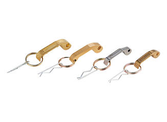
- Use locking clips for critical applications: Stainless steel locking clips (also called safety clips or cam lock pins) thread through holes in the cam arm ears to prevent accidental opening. These are required in many industrial and chemical settings and cost only a few cents each.
- Ground metal couplings when handling flammable fluids: Static electricity buildup during fuel transfer can ignite vapors. Bond and ground metal camlock couplings and hoses as per local fire and safety codes when handling petroleum or other flammable liquids.
- Inspect before every use in high-cycle applications: In agriculture, construction, or industrial transfer settings where couplings are connected and disconnected dozens of times per day, perform a visual inspection every time. Look for cam arm deformation, cam groove wear on the male adapter, and gasket condition.
- Do not use damaged couplings: A bent cam arm or a chipped coupling body should be removed from service immediately. The structural integrity of the locking mechanism cannot be guaranteed once the body is deformed.
Maintenance Practices That Extend Camlock Coupling Life
Quality camlock couplings made from stainless steel or aluminum can last many years with proper care. Neglected couplings deteriorate quickly, especially in outdoor or chemical environments.
After Every Use
- Flush couplings with clean water after handling fertilizers, chemicals, or food products
- Install dust caps and plugs on unused ends to prevent debris from entering the gasket seat or male adapter groove
- Check that cam arms close and open freely — stiffness indicates buildup or early corrosion
Periodic Inspection Schedule
- Replace gaskets at least once per season in outdoor agricultural applications, or every 90 days in high-cycle industrial use
- Lubricate cam arm pivot pins annually with a compatible lubricant — avoid petroleum-based lubricants on couplings used for water or food applications; use food-grade silicone grease instead
- Check the cam groove depth on male adapters — if the groove shows visible wear or metal removal, the adapter should be replaced, as a shallow groove will not hold the cam arms reliably
- For aluminum couplings in contact with alkaline solutions or seawater, inspect annually for white powdery corrosion (aluminum oxide). Light oxidation is normal; deep pitting is a sign to replace the fitting
Storage
Store camlock couplings in a cool, dry location away from direct sunlight when not in use. UV exposure degrades rubber gaskets and, over long periods, can embrittle polypropylene coupling bodies. Keep caps on both ends during storage to protect gasket seats and male adapter grooves from dust and physical damage. Hanging couplings on a pegboard or storing them in labeled bins sorted by size and type avoids the fumbling and misidentification that leads to installation errors in the field.
Choosing the Right Camlock Coupling for Your Application
With dozens of combinations of size, type, and material available, selecting the correct camlock coupling before installation saves time, money, and rework. Here is a practical decision framework:
- Identify the fluid: What are you transferring? Water, fuel, fertilizer, food product, chemical? This determines both the coupling body material and the gasket material.
- Determine the operating pressure: What is the maximum pressure in your system, including surges? Select a coupling rated comfortably above this figure — a safety margin of at least 25% above working pressure is advisable.
- Measure the connection points: Is the existing connection a hose shank, a male NPT thread, or a female NPT thread? This tells you which type (A through F) you need.
- Confirm the size: Measure the inner diameter of the hose or the thread size on the existing pipe. Do not assume a "2-inch system" uses 2-inch fittings everywhere — check each connection point.
- Consider the environment: Outdoor UV exposure, saltwater proximity, extreme temperatures, and frequency of connection cycles all influence the best material choice.
Spending five minutes on this checklist before ordering or grabbing hardware from a shelf is the difference between a system that works reliably for years and one that leaks on first use. Camlock couplings are a simple, well-engineered solution — but only when the right one is chosen and installed correctly.