英语
英语 俄语
俄语Content
- 1 How to Install a Cam Lock: The Short Answer
- 2 What Is a Camlock Coupling and Why Installation Matters
- 3 Camlock Coupling Types: Choosing the Right Configuration Before You Install
- 4 Materials and Gasket Selection: Getting This Right Protects Your Entire System
- 5 Step-by-Step: How to Install a Camlock Coupling Correctly
- 5.1 Step 1 — Depressurize and Isolate the System
- 5.2 Step 2 — Inspect Both Parts
- 5.3 Step 3 — Open the Cam Arms Fully
- 5.4 Step 4 — Insert the Adapter into the Coupler
- 5.5 Step 5 — Close the Cam Arms
- 5.6 Step 6 — Apply Safety Clips or Locking Devices (Where Required)
- 5.7 Step 7 — Pressure Test Before Full Operation
- 6 How to Install the Threaded End of a Camlock Coupling onto a Pipe
- 7 Common Installation Mistakes and How to Avoid Them
- 8 Pressure and Temperature Ratings: What the Specifications Actually Mean
- 9 Maintenance, Inspection, and Service Life of Camlock Couplings
- 10 Installing Camlock Couplings in Specific Industries: Key Differences
- 11 Troubleshooting: When Your Camlock Connection Leaks
- 12 Frequently Asked Questions About Installing Camlock Couplings
- 12.1 Do I need tools to install a camlock coupling?
- 12.2 Can aluminum and stainless camlock couplings be used together?
- 12.3 How often should I replace the gasket in a camlock coupler?
- 12.4 Is it safe to install a camlock coupling on a live (pressurized) line?
- 12.5 What is the difference between Type A and Type B camlock couplings?
- 12.6 Why do my cam arms feel stiff or hard to close?
How to Install a Cam Lock: The Short Answer
Installing a camlock coupling is straightforward: align the female coupler with the male adapter, push them together until the cams engage, then press the cam arms down firmly until they lock flat against the body. No tools are required for standard dry-break connections. The entire process takes under 10 seconds for an experienced operator — but doing it correctly the first time depends on selecting the right cam lock type, inspecting the gasket, and confirming the arms are fully seated.
Below you'll find a complete, step-by-step breakdown covering every cam lock type, material considerations, torque and pressure ratings, common mistakes, and maintenance procedures so your connections stay leak-free under demanding conditions.
What Is a Camlock Coupling and Why Installation Matters
A camlock coupling — also called a cam-and-groove coupling — is a quick-connect fitting widely used in industrial fluid transfer, agriculture, oil and gas, fire suppression, chemical processing, and food-grade applications. The design was standardized under MIL-C-27487 (a U.S. military specification) and later adopted globally through standards such as ISO 4038 and EN 14420-7.
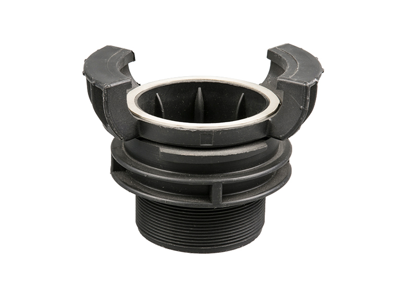
Each camlock coupling system consists of two mating parts:
- Coupler (female part) — contains the cam arms and the groove that locks around the adapter groove.
- Adapter (male part) — the grooved end that inserts into the coupler.
The cam arms on the coupler pivot over the groove on the adapter and, when pressed down, create a secure, leak-resistant seal backed by an internal gasket. Misaligned installation — or a worn gasket — is the leading cause of drips, spills, and unplanned downtime in fluid transfer systems. A proper installation procedure reduces that risk to near zero.
Camlock couplings are available in sizes ranging from ½ inch to 6 inches (and larger in custom configurations), with pressure ratings typically between 75 PSI and 250 PSI depending on material, size, and temperature.
Camlock Coupling Types: Choosing the Right Configuration Before You Install
There are seven standard camlock coupling types, each defined by how the coupler or adapter terminates on the opposite end from the cam-and-groove connection. Identifying the correct type before installation prevents costly mistakes and compatibility failures.
| Type | Part | Other End Connection | Common Use |
|---|---|---|---|
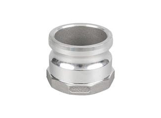
| Type A | Adapter | Male BSP / NPT thread | Tank outlets, pumps |
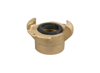
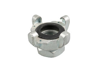
| Type B | Coupler | Female BSP / NPT thread | Hose ends, manifolds |
| Type C | Coupler | Hose shank (barbed) | Flexible hose lines |
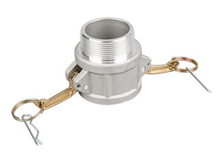
| Type D | Coupler | Female BSP / NPT thread | Pipe systems |
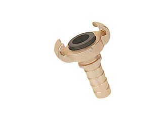
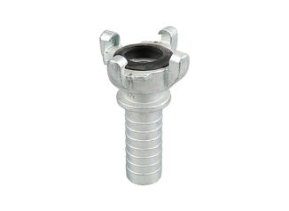
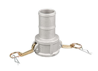
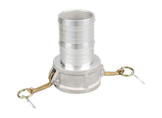
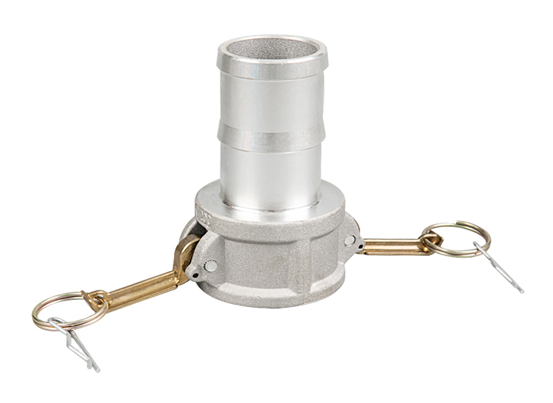
| Type E | Adapter | Hose shank (barbed) | Suction/discharge hoses |
| Type F | Adapter | Male BSP / NPT thread | High-pressure pipe runs |
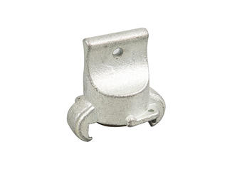
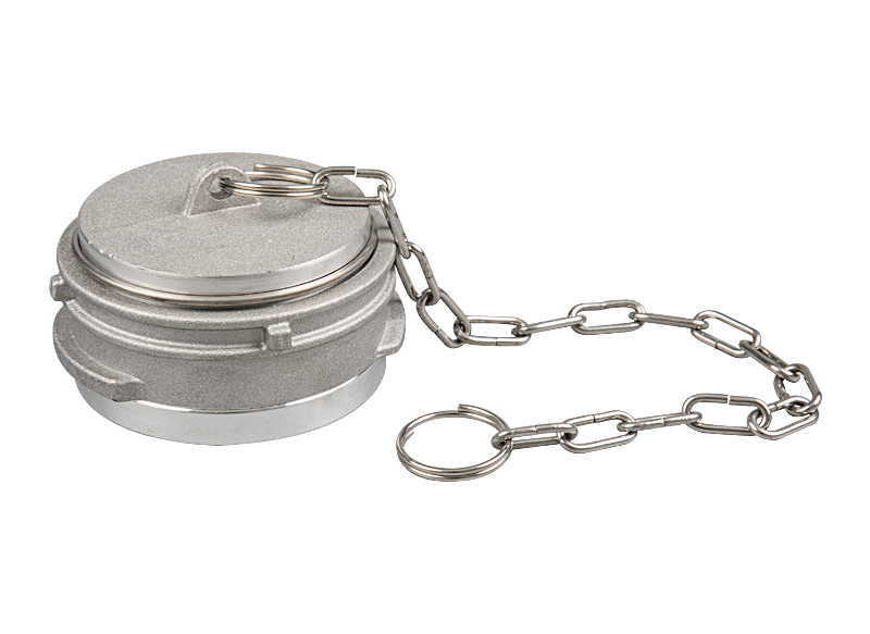
| Type DC | Dust Cap | N/A | Sealing open coupler ends |
Before installing any camlock coupling, verify that both parts share the same nominal size. A 2-inch coupler will not properly lock onto a 2½-inch adapter, even if the cam arms appear to close — the internal gasket won't seat, and the connection will fail under pressure.
Materials and Gasket Selection: Getting This Right Protects Your Entire System
Camlock couplings are manufactured in several materials, each suited to different chemical environments, temperatures, and pressures. Using the wrong material — even with a perfectly executed installation — leads to rapid degradation, contamination, or catastrophic failure.
Coupling Body Materials
- Aluminum — lightweight, cost-effective, suitable for water, fuels, and mild chemicals. Not compatible with strong acids or chlorinated compounds. Working temperature range typically −40°C to +120°C.
- Stainless Steel (304/316) — excellent corrosion resistance, suitable for food-grade, pharmaceutical, and aggressive chemical applications. 316 SS offers better resistance to chlorides.
- Brass — good for water, compressed air, and petroleum. Not suitable for ammonia or high-pressure steam.
- Polypropylene (PP) — lightweight and chemically resistant to many acids and solvents. Maximum working pressure typically around 75 PSI.
- PVDF (Kynar) — high purity, UV resistant, suitable for highly corrosive chemicals and semiconductor applications.
Gasket Material Selection
The internal gasket inside the coupler is what creates the seal. Choosing the correct gasket material is just as critical as the body material. Using a Buna-N (NBR) gasket with a solvent like acetone will cause the gasket to swell and fail within minutes.
- Buna-N (NBR) — best for petroleum-based fluids, water, and mild chemicals. Temperature range: −40°C to +120°C. The most common default gasket.
- EPDM — excellent for water, steam, ozone, and many dilute acids. Poor resistance to petroleum products.
- Viton (FKM) — high chemical resistance; suitable for aggressive acids, fuels, and high temperatures up to +200°C.
- PTFE (Teflon) — chemically inert across almost all substances. Used in food, pharmaceutical, and ultra-pure applications.
- Silicone — food-grade applications, good for hot water and steam up to +200°C, but poor hydrocarbon resistance.
Before installing a camlock coupling, physically inspect the gasket. A compressed, cracked, or hardened gasket — even on a new coupling stored improperly — will not seal. Replace any gasket that shows surface deformation, flattening, or chemical discoloration before making the connection.
Step-by-Step: How to Install a Camlock Coupling Correctly
The following procedure applies to standard cam-and-groove connections — the coupler-to-adapter join at the heart of every camlock coupling system. For thread-end installation (attaching the non-cam end to a pipe or hose), see the section below.
Step 1 — Depressurize and Isolate the System
Never install or disconnect a camlock coupling while the line is pressurized or flowing. Close all upstream and downstream valves, bleed any residual pressure using the system's vent point, and verify that the gauge reads zero. Residual pressure as low as 5 PSI can cause the coupler to eject violently when the cam arms are opened. In chemical environments, flush the line with an appropriate neutralizing agent before working on connections.
Step 2 — Inspect Both Parts
Lay out the coupler and adapter side by side and check:
- The cam arms pivot freely and spring back when released. Stiff or bent cam arms indicate wear or damage — replace the coupler.
- The groove on the adapter is clean, undamaged, and free of debris. A nicked groove will prevent the cam arms from seating flush.
- The internal gasket in the coupler is present, seated evenly in its groove, and not cracked, swollen, or hardened.
- Both parts are the same nominal size and from the same standard (MIL-SPEC, EN, etc.).
- Neither part shows visible corrosion pitting, cracks, or deformation of the cam lugs.
Step 3 — Open the Cam Arms Fully
Lift both cam arms on the coupler to the fully open position — perpendicular to the body or slightly past vertical. This retracts the cam cams clear of the internal groove so the adapter can be inserted without resistance. On larger couplings (3 inches and above), you may feel spring tension in the arms; this is normal.
Step 4 — Insert the Adapter into the Coupler
Push the male adapter straight into the open coupler in a single, smooth motion. There is no rotational alignment required — camlock couplings are designed for full 360° symmetry. The adapter should slide in until its groove is approximately flush with the cam lug contact points on the coupler body. You will often feel a slight "click" or resistance increase as the adapter seats against the gasket.
Do not force the adapter in at an angle. Cross-threading or cocking the adapter before the arms are closed will damage the gasket and create a leak path even when the arms appear locked.
Step 5 — Close the Cam Arms
Press both cam arms down simultaneously — or one at a time if space is restricted — until they lie flat against the coupler body. Each arm should close with a firm snap. A properly sized and undamaged camlock coupling should require hand pressure only; if significant force is needed, the parts may be incompatible in size or the adapter groove is worn.
Once closed, visually confirm that:
- Both arms are completely flat against the coupler body, not angled upward.
- The cam lobes on both arms are fully engaged in the adapter groove — no visible gap between the cam and the groove face.
- The adapter cannot be pulled out with moderate hand force — tug firmly to confirm engagement.
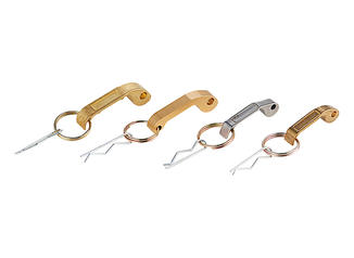
Step 6 — Apply Safety Clips or Locking Devices (Where Required)
In applications involving pressures above 50 PSI, vibration, hazardous chemicals, or food-grade processes, a safety clip, locking pin, or wire lock should be installed through the holes in the cam arm lugs. This secondary locking mechanism prevents accidental cam arm opening due to vibration, pressure surges, or unintentional contact.
Some camlock coupling manufacturers offer stainless steel R-clips or locking rings that snap into place without tools. In high-pressure or critical applications, safety locking is not optional — it is required under OSHA 29 CFR 1910.119 (Process Safety Management) for hazardous chemical systems.
Step 7 — Pressure Test Before Full Operation
Before returning the system to full operating pressure, slowly open the upstream valve to allow pressure to build gradually. Observe the coupler body and the cam arm/groove interface for any weeping or drips at 25%, 50%, and 100% of working pressure. If any leakage is detected, depressurize immediately, open the cam arms, re-inspect the gasket, and reconnect.
A new camlock coupling on a clean adapter with a fresh gasket should produce a completely dry connection at rated pressure without any adjustment beyond what is described above.
How to Install the Threaded End of a Camlock Coupling onto a Pipe
The cam-and-groove end gets most of the attention, but the opposite threaded end — whether BSP, NPT, or a hose shank — must also be installed correctly to achieve a leak-free system. A poor thread connection will undermine even a perfect cam connection downstream.
Installing NPT or BSP Threaded Camlock Adapters
- Clean the pipe thread thoroughly — remove any old thread sealant, rust, or debris with a wire brush.
- Apply PTFE thread tape (for NPT) or an appropriate thread sealant compound (for BSP parallel threads) evenly across the male thread, starting at the first thread and wrapping in the direction of thread travel — clockwise when facing the thread end.
- Apply 2–3 wraps of PTFE tape for standard connections, more for coarser threads. On stainless steel to stainless steel connections, use an anti-seize compound instead of PTFE to prevent galling.
- Hand-tighten the coupling onto the pipe, then use a wrench to tighten an additional 2–3 turns past hand-tight for NPT, or to the torque specified by the manufacturer for BSP.
- Do not over-tighten — NPT connections seal on the taper, and excessive torque will crack aluminum couplings or deform the thread on plastic bodies. As a reference, a 1-inch NPT aluminum camlock adapter should be tightened to approximately 20–30 Nm.
Installing Camlock Couplings on Hose Shanks (Type C and Type E)
Barbed hose shank camlock couplings require either a hose clamp or a ferrule crimp to secure the hose:
- Hose clamp method: Lubricate the hose shank and the hose bore with water or mild soap (not petroleum lubricants for rubber hose). Push the hose fully over the shank until the hose end is past the last barb. Position a stainless steel worm-drive hose clamp over the hose body above the last barb and tighten to the hose manufacturer's recommended torque — typically 4–6 Nm for 1–2 inch suction hose.
- Ferrule crimp method: For higher-pressure or industrial-grade assemblies, a hydraulic crimping tool is used to compress an aluminium or steel ferrule around the hose, providing superior pull-out resistance compared to hose clamps. Crimp dimensions must match the hose manufacturer's specification sheet exactly.
After assembly, perform a pull-out test: anchor the coupling body and apply a pull force equal to 2× the rated working pressure load along the hose axis. The hose should not slip or rotate on the shank.
Common Installation Mistakes and How to Avoid Them
Most camlock coupling failures in the field — leaks, disconnections, and contamination events — trace back to a small number of recurring installation errors. Understanding these specifically helps maintenance teams implement better procedures.
Mismatched Sizes
A 2-inch coupler appears to accept a 2½-inch adapter with some force, and the cam arms may even partially close. However, the cam lobes will not fully engage the groove, leaving the connection vulnerable to pull-out at pressures as low as 10–15 PSI. Always verify size markings on both parts before connection — they are typically stamped on the body.
Worn or Missing Gaskets
This is the single most common cause of cam lock leaks. Gaskets in heavy-use couplings should be replaced every 6–12 months or after any visible chemical exposure or physical deformation. Keep a stock of replacement gaskets in all relevant materials on site. In food processing environments, FDA-compliant gaskets must be replaced according to HACCP maintenance schedules.
Partially Closed Cam Arms
A cam arm that looks closed from a distance may still be angled 5–10° above the body, particularly on older couplings where the cam spring has weakened. This partial engagement reduces holding force dramatically. Always perform the visual flat-check and the hand-tug test after closing arms.
Cross-Material Compatibility Errors
Mixing an aluminum coupler with a stainless steel adapter in a saltwater or chlorinated environment accelerates galvanic corrosion dramatically. Within weeks, the aluminum component can develop pitting that compromises both the cam arm pivot and the groove engagement surface. Match materials where possible; where dissimilar metals must be used, apply an isolating compound or use polymer couplings.
Operating While Connected Under Full Flow
Camlock couplings are not designed to be connected or disconnected under flow (unlike some specialized dry-break couplings). Attempting to open cam arms on a pressurized line causes rapid depressurization, spills, and risk of serious injury. Always shut the valve, bleed pressure, and verify zero pressure before working with any camlock connection.
Skipping Safety Clips in Vibration-Heavy Environments
Pump discharge lines, compressor outlets, and tanker truck connections all generate significant vibration. Without a safety clip, cam arms can vibrate open over time. Incidents documented in chemical plant safety audits have shown cam arm opening in as few as 4 hours of continuous vibration without secondary locking. Always use clips in these environments.
Pressure and Temperature Ratings: What the Specifications Actually Mean
Camlock coupling ratings are not universal — they vary by material, size, and the specific standard the coupling was manufactured to. Treating every camlock as rated for 150 PSI is a common and dangerous assumption.
| Material | ½"–1" | 1½"–2" | 3"–4" | 6" |
|---|---|---|---|---|
| Aluminum | 250 PSI | 150 PSI | 100 PSI | 75 PSI |
| Stainless Steel | 250 PSI | 200 PSI | 150 PSI | 100 PSI |
| Brass | 250 PSI | 150 PSI | 100 PSI | 75 PSI |
| Polypropylene | 100 PSI | 75 PSI | 50 PSI | 35 PSI |
These ratings apply at ambient temperature. Elevated temperatures reduce pressure ratings significantly — a polypropylene camlock coupling rated for 75 PSI at 20°C may only handle 35 PSI at 60°C. Always consult the manufacturer's pressure-temperature derating curve when operating above 40°C.
Additionally, pressure surges (water hammer) can momentarily spike pressure to 2–4× the steady-state line pressure. For lines with rapid valve closures or pump start/stop cycles, select camlock couplings with a rated pressure at least 2× your maximum steady-state operating pressure.
Maintenance, Inspection, and Service Life of Camlock Couplings
A well-maintained camlock coupling can last 10 years or more in low-cycle, non-corrosive applications. In high-cycle industrial use — fuel transfer stations, for example, where a coupling may be made and broken 20 times per day — replacement of gaskets and inspection of the cam arms should be built into monthly maintenance routines.
Regular Inspection Points
- Cam arms: Check pivot pins for wear or elongation. Arms should snap closed without excessive play. If the arm feels sloppy in the pivot, replace the coupler.
- Cam lobes: Inspect the contact surface on the underside of each cam arm for flattening or grooving. Worn cam lobes reduce clamping force.
- Adapter groove: The groove profile should be sharp and even. A worn or rounded groove reduces cam engagement and holding force by up to 40%.
- Gasket: Remove and inspect the gasket every 3–6 months in active service. Replace immediately if it shows compression set, cracking, swelling, or surface tackiness.
- Body and threading: Look for cracks, corrosion pitting, and thread deformation on the non-cam end.
Cleaning and Storage
After service in chemical, food, or petroleum environments, flush camlock couplings with the appropriate cleaning solution — water and neutral detergent for food-grade, solvent flush for fuel systems, or a neutralizing agent for acid/base services. Dry thoroughly and store with dust caps on both the coupler and adapter ends. Store in a cool, UV-protected location; prolonged UV exposure degrades polypropylene and many gasket materials.
Lubricate cam arm pivot pins annually with a compatible lubricant — white lithium grease for general use, food-grade lubricant (NSF H1 rated) for food processing environments. Never use petroleum-based lubricants near EPDM or silicone gaskets.
Installing Camlock Couplings in Specific Industries: Key Differences
While the mechanical installation procedure is the same across industries, regulatory requirements, material selections, and secondary safety measures vary significantly depending on the application.
Agriculture and Irrigation
Aluminum camlock couplings with Buna-N gaskets are the standard for irrigation water transfer. Connections are typically made and broken multiple times per day during irrigation runs. Dust and sand ingress is the primary wear mechanism — rinse couplings after each use and store with caps. In fertigation systems where fertilizer solutions pass through, rinse with clean water after each application to prevent internal salt buildup that degrades gaskets.
Chemical Processing
Chemical service demands careful material matching as described above. Additionally, chemical plant installations typically require color-coded cam lock systems — different colors for different media — to prevent cross-contamination. For example, yellow couplings for sulfuric acid lines, blue for water, red for flammable liquids. Safety clips and secondary retention cables are mandatory in most process plants. Personal protective equipment (PPE) — chemical-resistant gloves, face shield, apron — must be worn when making or breaking connections on chemical lines, even after depressurization.
Food and Beverage
Food-grade applications require 316 stainless steel couplings with FDA-compliant PTFE or silicone gaskets. All contact surfaces must be smooth (typically Ra ≤ 0.8 µm) to prevent biofilm formation. Installation and removal must occur as part of a documented CIP (Clean-in-Place) protocol. Cam lock couplings in food plants should be inspected after every production run for gasket integrity; a compromised gasket is a potential food safety hazard.
Fuel and Petroleum Transfer
Aluminum or stainless camlock couplings with Viton gaskets are standard for fuel transfer. In tanker truck loading/unloading operations, the camlock coupling should be bonded and grounded before connection to dissipate static charges that could ignite fuel vapors. The bonding cable connects from the tanker to a grounding rod, with resistance verified at below 10 ohms before any camlock connection is made. API RECOMMENDED PRACTICE 1004 provides detailed guidance on petroleum tanker connections.
Troubleshooting: When Your Camlock Connection Leaks
A leaking camlock coupling after installation almost always has one of the following root causes, each with a specific fix:
- Leak at the cam-groove interface: Gasket is worn, missing, or incompatible. Depressurize, open arms, replace gasket, reconnect.
- Leak with cam arms fully closed: Adapter groove is worn and cam lobes are not making full contact. Replace the adapter; do not continue to use a worn adapter — increasing arm closing force will not fix the root problem.
- Leak at the threaded end: Insufficient PTFE tape, crossed threads, or damaged thread profile. Disassemble, clean threads, re-tape, and reassemble.
- Leak that develops during operation but not at start-up: Thermal expansion at elevated temperatures is compressing the gasket. Use a gasket material with a higher temperature rating or a spring-energized seal design for high-temperature applications.
- Intermittent leak under vibration: Cam arms opening slightly. Fit safety clips immediately and inspect cam arm pivot pins for wear.
Frequently Asked Questions About Installing Camlock Couplings
Do I need tools to install a camlock coupling?
No tools are needed for the cam-and-groove connection itself — that is the primary advantage of camlock coupling design. For the threaded end (pipe or hose), standard pipe wrenches or hose clamp screwdrivers are required. For ferrule crimp assemblies, a hydraulic crimping tool is needed.
Can aluminum and stainless camlock couplings be used together?
Technically they will connect — camlock couplings of the same size are designed to be interchangeable across materials. However, in corrosive or wet environments, mixing aluminum and stainless steel creates a galvanic cell that accelerates corrosion of the aluminum part. In dry or low-humidity applications, mixing is generally acceptable for short-term use.
How often should I replace the gasket in a camlock coupler?
In light-duty applications (occasional connections, water service), gaskets can last 2–3 years. In high-cycle industrial use or chemical service, replace gaskets every 6–12 months or whenever a visual inspection shows any deformation. Always keep spare gaskets in all materials used on your site.
Is it safe to install a camlock coupling on a live (pressurized) line?
No. Standard camlock couplings must only be connected or disconnected with the line depressurized and flow stopped. Attempting to connect or open cam arms on a pressurized line is extremely dangerous and can result in serious injury. Specialized dry-break or breakaway couplings are available for applications requiring live-line connection, but these are a different product category from standard camlock couplings.
What is the difference between Type A and Type B camlock couplings?
Type A is a male adapter with a male threaded (BSP or NPT) end — it screws into a female port. Type B is a female coupler with a female threaded end — it connects to a male pipe nipple. Both types have the cam-and-groove interface on one end; the difference is only in the threaded end's gender. In a typical installation, a Type A adapter might be fitted to a tank outlet, and a Type B coupler connects the hose assembly to the pipe.
Why do my cam arms feel stiff or hard to close?
Stiff cam arms are usually caused by one of three things: the adapter size is slightly wrong (too large), the cam arm pivot pins need lubrication, or the cam lobes and adapter groove have built-up contamination. Clean and lubricate the pivot pins, clean the adapter groove, and verify the size match. If arms remain stiff after cleaning on a correct-size matched pair, inspect the cam lobe geometry for deformation — worn or bent lobes require coupler replacement.