英语
英语 俄语
俄语Content
- 1 How to Install Camlock Fittings: The Direct Answer
- 2 Understanding Camlock Fitting Types Before You Install
- 3 Tools and Inspection Steps Before Installation
- 4 Step-by-Step: How to Install Camlock Fittings onto a Threaded Port
- 5 Step-by-Step: How to Install Camlock Fittings onto a Hose
- 6 How to Connect Cam and Groove Couplings: The Coupling Action Explained
- 7 Gasket Selection and Replacement for Camlock Couplings
- 8 Pressure Testing After Camlock Fitting Installation
- 9 Common Camlock Fitting Installation Mistakes and How to Avoid Them
- 10 Camlock Fitting Installation in Specific Industries
- 11 Maintenance Schedule for Camlock Couplings
- 12 Frequently Asked Questions About Camlock Fitting Installation
- 12.1 Can you connect camlock fittings from different manufacturers?
- 12.2 How do you know if a camlock fitting is fully locked?
- 12.3 Why is my camlock fitting leaking even though the arms are locked?
- 12.4 What is the maximum operating pressure for camlock fittings?
- 12.5 Can camlock fittings be used for vacuum service?
- 12.6 How do I remove a stuck or corroded camlock fitting?
- 12.7 Do camlock fittings need to be lubricated?
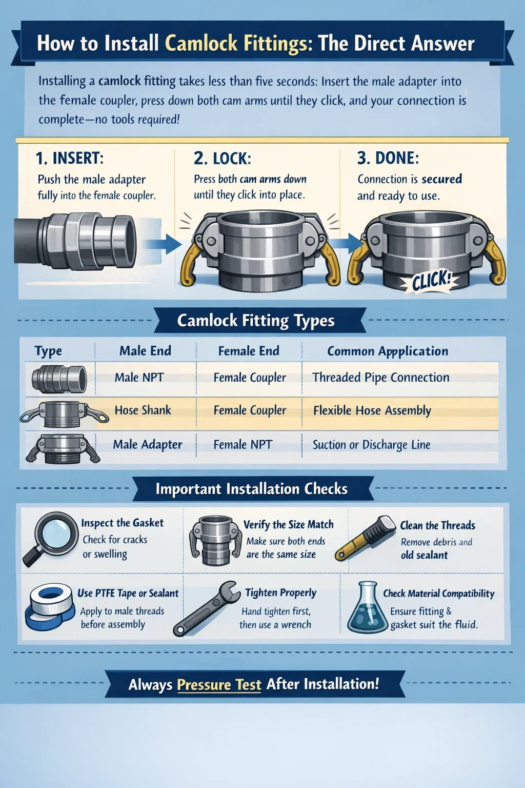
How to Install Camlock Fittings: The Direct Answer
Installing a camlock fitting takes less than five seconds under normal conditions. You insert the male adapter (plug) into the female coupler, press down both cam arms simultaneously until they click into the locked position, and the connection is complete — no tools required. To disconnect, lift both arms at the same time and pull the plug free. That is the core of camlock coupling installation.
However, a five-second action done incorrectly causes leaks, cross-threading, gasket failures, and in high-pressure or chemical-transfer applications, serious safety incidents. The sections below cover every detail you need to install camlock fittings correctly the first time, across different materials, sizes, and working environments.
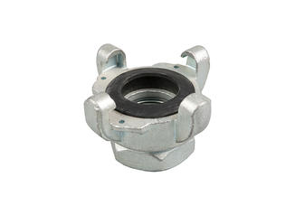
Understanding Camlock Fitting Types Before You Install
Camlock fittings — also called cam and groove couplings — follow MIL-C-27487 and EN 14420-7 standards. There are seven standard configurations. Knowing which type you have determines how the installation proceeds.
| Type | Male End | Female End | Typical Application |
|---|---|---|---|
| Type A | Coupler (female) | Male NPT thread | Threaded pipe connections |
| Type B | Coupler (female) | Female NPT thread | Female-threaded pipe ends |
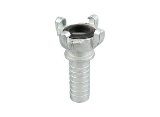
| Type C | Coupler (female) | Hose shank (barb) | Flexible hose assembly |
| Type D | Coupler (female) | Plain end (weld/insert) | Welded or insert pipe connections |
| Type E | Male adapter (plug) | Male NPT thread | Tank outlets, pumps |
| Type F | Male adapter (plug) | Female NPT thread | Suction or discharge lines |
| Type DC | Dust cap | Fits coupler | Storage/end protection |
Before installation, confirm the type designation stamped or cast into the body. Using a Type E where a Type F is required changes the thread engagement direction and will result in an incomplete seal.
Camlock fittings are manufactured in aluminum, stainless steel (304 and 316), brass, polypropylene, and nylon. The material affects not only chemical compatibility but also how much force is required to seat the cam arms. Aluminum camlock couplings are the most common in general water and fuel transfer. Stainless steel camlock fittings are preferred in food-grade, pharmaceutical, and corrosive chemical environments. Polypropylene camlock fittings are used where metal contamination is unacceptable or where the medium is highly acidic.
Tools and Inspection Steps Before Installation
One of the defining advantages of cam and groove fittings is that they require no tools for the coupling action itself. However, the preliminary steps — attaching the fitting to a hose, pipe, or threaded port — do require tools and proper technique.
What You Will Need
- Pipe wrench or adjustable wrench (for threaded connections)
- Hose clamps and clamp driver (for hose shank/barb types)
- PTFE thread tape or thread sealant compound
- Replacement gaskets matching the camlock size and material
- Clean cloth or lint-free wipe
- Torque wrench (for high-pressure or critical service applications)
- Compatible lubricant for stainless steel fittings (anti-galling compound)
Pre-Installation Inspection Checklist
Never skip inspection. A single cracked cam arm or a swollen gasket is enough to cause a failure under pressure. Check the following before every installation:
- Gasket condition: The gasket seated inside the female coupler must be free of cracks, deformation, chemical swelling, or flat spots. In high-cycle operations, gaskets should be replaced every 90–180 days regardless of visible condition.
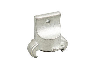
- Cam arm integrity: Both arms must spring back to the open position freely. A bent or stiff arm will not lock fully and may release under pressure.
- Groove and lug condition: The grooves on the male adapter must be clean and free of burrs or corrosion. Damaged grooves prevent the cam arms from seating flush.
- Size match: Verify that both the coupler and the adapter are the same nominal size. Standard camlock fittings range from ½ inch to 6 inches. Attempting to connect mismatched sizes damages both components and will not seal.
- Material compatibility: If you are transferring a chemical, confirm that the fitting material and gasket material are both rated for that chemical. For example, EPDM gaskets are incompatible with petroleum products; use Viton or Buna-N instead.
- Thread condition (for threaded types): Inspect the NPT threads for cross-threading, corrosion, or damage. Run a thread chaser if necessary before applying sealant.
Step-by-Step: How to Install Camlock Fittings onto a Threaded Port
This is the most common installation scenario — attaching a Type A, B, E, or F camlock fitting to an NPT-threaded pipe, valve, or tank outlet.
- Clean the threads. Wipe both the male and female thread surfaces with a clean cloth. Any debris, old sealant, or corrosion must be removed. Use a wire brush if necessary.
- Apply PTFE tape or thread sealant. Wrap PTFE tape clockwise around the male thread, starting at the first thread and working toward the end. Overlap each wrap by approximately 50%. Use 2–3 wraps for standard service; 4–5 wraps for pressurized or high-vibration applications. For liquid sealant compounds, apply a thin, even coat and allow it to become tacky before threading.
- Thread the fitting by hand first. Start threading by hand to avoid cross-threading. If the fitting does not turn freely for the first 2–3 threads, stop and realign. Cross-threading aluminum camlock fittings is a common and costly mistake.
- Tighten with a wrench. Once hand-tight, use a wrench to tighten an additional 1.5 to 2.5 turns for NPT connections. Do not over-torque. For ½-inch aluminum fittings, typical torque is 20–25 ft-lbs. For 2-inch stainless steel fittings, 60–75 ft-lbs is common. Always follow the manufacturer's specification when available.
- Position the fitting for cam arm access. Before final tightening, orient the coupler so that the cam arms face a direction that allows easy manual operation after the hose is connected. This is especially important in confined spaces.
- Verify the gasket is seated. Look into the female coupler and confirm the gasket sits flush and level in its groove. A tilted or partially seated gasket will leak under pressure even if the cam arms lock correctly.
Step-by-Step: How to Install Camlock Fittings onto a Hose
Type C and Type D camlock fittings attach to flexible hose via barb or smooth shank ends. This installation is common in irrigation, chemical transfer, and fuel handling setups where hoses are frequently connected and disconnected.
- Cut the hose end square. Use a sharp hose cutter or hacksaw with a guide to make a clean, 90-degree cut. A diagonal or ragged cut prevents the hose from seating fully over the barb and creates leak paths.
- Soften the hose end if needed. Dip the cut hose end in hot water (60–70°C / 140–158°F) for 30 seconds to soften rubber or PVC hoses. This makes it significantly easier to push the hose over the barb without using excessive force or lubricant that may contaminate the medium.
- Push the hose over the barb. Insert the camlock fitting shank into the hose end and push until the hose end is flush with or just past the first barb ridge. For larger diameters (2 inches and above), a hose insertion tool or bench vise may be necessary.
- Position the hose clamps. Slide a hose clamp over the hose before inserting the fitting (if using worm-drive clamps). Position it over the barb section, approximately 5–10 mm from the fitting flange. For high-pressure applications above 150 PSI, use two clamps spaced 10–15 mm apart.
- Tighten the clamps evenly. Tighten the clamp until snug, then torque to the manufacturer's specification. For typical worm-drive clamps on a 1-inch hose, 20–30 in-lbs is the standard range. Do not over-tighten — deforming the hose wall reduces grip and can crack the barb on polypropylene camlock fittings.
- Allow cooldown before pressure test. If you heated the hose to soften it, allow it to cool to ambient temperature before pressure testing. Hot rubber or PVC temporarily expands, and clamp torque may need adjustment after cooling.
How to Connect Cam and Groove Couplings: The Coupling Action Explained
Once both the male adapter and the female coupler are installed on their respective hoses, pipes, or ports, the coupling step itself is straightforward. But small errors here are the most common source of failures in the field.
The Correct Coupling Procedure
- Open the cam arms fully. Before inserting the male adapter, lift both cam arms to the fully open (upright or horizontal, depending on design) position. This retracts the cam lobes inside the coupler so the adapter can enter freely.
- Align the adapter with the coupler. Hold the male adapter straight in line with the female coupler. Do not approach at an angle. Off-axis insertion can pinch or dislodge the gasket, which will cause leakage even with the arms locked.
- Insert the adapter fully. Push the male adapter straight into the female coupler until it is fully seated. You should feel a slight resistance as the adapter contacts the gasket. The adapter must be fully inserted before the arms are closed — partial insertion is the single most common installation error.
- Close both cam arms simultaneously. Press both cam arms down together in a single smooth motion. The cam lobes engage the grooves on the male adapter and pull it tightly against the gasket as the arms close. You should hear a click or feel a definite snap as each arm locks into place.
- Verify both arms are fully locked. After closing, try to lift each arm individually. A properly locked arm should not lift without deliberate force on both arms at once. If either arm lifts easily, the fitting is not fully engaged — remove and re-insert before pressurizing.
Why Partial Insertion Causes Failures
When the male adapter is not fully inserted, the cam lobes lock onto the grooves at an angle. This creates an asymmetric load on the gasket — one side compresses more than the other. At low pressures (below 20 PSI), the system may appear to hold. At operational pressure, the uneven load causes the gasket to extrude from one side, releasing the fluid. In petroleum or chemical transfer, this scenario creates both financial loss and safety hazards. Industry maintenance records show that partial insertion accounts for approximately 40–60% of camlock fitting failures reported in field service audits.
Gasket Selection and Replacement for Camlock Couplings
The gasket is the only element that creates the fluid seal in a camlock coupling. The metal-to-metal contact between the adapter and coupler body does not seal — the gasket does all the work. Selecting the wrong gasket material, or failing to replace worn gaskets, is a guaranteed path to leaks.
| Gasket Material | Temperature Range | Compatible Media | Not Suitable For |
|---|---|---|---|
| Buna-N (NBR) | -40°C to +120°C | Petroleum, oils, fuel, water | Ozone, ketones, strong acids |
| EPDM | -40°C to +150°C | Water, steam, acids, alkaline | Petroleum products, solvents |
| Viton (FKM) | -20°C to +200°C | Fuels, solvents, acids, hydraulic fluids | Ketones, low-molecular-weight esters |
| PTFE | -200°C to +260°C | Most chemicals, acids, solvents | Fluorinated compounds, molten alkali metals |
| Silicone | -60°C to +230°C | Food, beverage, pharmaceuticals | Petroleum products, dynamic sealing |
| Neoprene | -40°C to +100°C | Refrigerants, mild oils, water | Aromatic solvents, strong oxidizers |
How to Replace a Camlock Gasket
- Disconnect the camlock coupling and open the cam arms fully.
- Use a flat-head screwdriver or pick tool to lift the old gasket out of the groove in the female coupler. Do not gouge the gasket seat surface.
- Clean the gasket groove with a lint-free cloth. Remove any residue, debris, or chemical deposits.
- Confirm the replacement gasket is the correct size and material for your application. Gasket sizes are standardized by the coupling's nominal diameter (e.g., a 2-inch camlock uses a 2-inch gasket).
- Press the new gasket into the groove by hand, working around the circumference. It should seat evenly with no raised sections. Do not use silicone grease or petroleum-based lubricant on EPDM or rubber gaskets unless the product is explicitly rated for that material.
- Reconnect and test before returning to service.
Pressure Testing After Camlock Fitting Installation
Never assume a newly installed or reconnected camlock fitting is leak-free without a pressure test. The test procedure depends on the working pressure of your system and the fluid being transferred.
Standard Hydrostatic Test Procedure
- Fill the system with water (not the operational fluid) and purge all air. Air in the system causes test pressure spikes that can mask leaks.
- Pressurize slowly to 1.5 times the maximum working pressure of the camlock fitting. Most standard aluminum camlock couplings are rated at 100–250 PSI depending on size. A 1-inch aluminum camlock fitting typically has a working pressure of 200 PSI and a burst pressure above 800 PSI.
- Hold the test pressure for a minimum of 10 minutes. Inspect all camlock connections, hose clamps, and threaded joints visually. Check for moisture around the gasket seat area, which is the first sign of seepage.
- Depressurize slowly and drain the test fluid. Rapid depressurization can cause water hammer, which can dislodge gaskets or loosen recently tightened connections.
Low-Pressure Pneumatic Test (for Gas Systems)
For systems conveying gas or air, use a low-pressure pneumatic test at no more than 25 PSI. Apply soapy water or a commercially available leak detection fluid around every camlock joint. Bubbles indicate a leak. Never perform a high-pressure pneumatic test on camlock fittings without proper safety barriers — stored pneumatic energy in a pressurized system is far more dangerous than hydraulic.
Common Camlock Fitting Installation Mistakes and How to Avoid Them
Most camlock fitting failures in service are installation errors, not product defects. These are the mistakes that appear most frequently in maintenance logs and incident reports.
Connecting Under Pressure
Camlock fittings must never be connected or disconnected while the system is pressurized. The cam and groove design relies on the gasket compressing against a static surface. Under pressure, even a small amount of flow forces the gasket sideways as the adapter is inserted. This damages the gasket immediately and exposes the operator to fluid ejection. Always depressurize and drain the line before coupling or uncoupling.
Using Mismatched Materials
Connecting an aluminum female coupler to a stainless steel male adapter is mechanically possible — the dimensions are compatible — but creates a galvanic corrosion cell. In wet or humid environments, the aluminum component will corrode significantly faster than it would in a like-metal connection. Over 12–18 months in a moist environment, this corrosion can seize the cam arms or cause pitting in the sealing face. Use like materials throughout the coupling assembly.
Overtightening Threaded Connections
NPT threads are tapered and self-sealing when correctly applied with sealant. Overtightening does not create a better seal — it cracks the fitting body. This is especially common with polypropylene camlock fittings, which have a lower tensile strength than metal. Cracked polypropylene bodies may hold pressure initially but fail catastrophically under thermal cycling or UV exposure.
Ignoring Swivel Usage on Rigid Pipe
When a camlock fitting is installed on rigid pipe and the hose on the opposite end is routed at an angle, the hose torques the coupling continuously. Over time, this repeated torque cracks weld-neck fittings and loosens threaded connections. Use a swivel-end camlock adapter in these situations to allow the hose to rotate freely without transmitting torque to the pipe connection.
Storing Couplings Without Dust Caps
Uncapped couplers accumulate debris in the gasket groove and corrosion on the coupling interior. A single piece of grit on the gasket seating face is enough to cause a leak that requires gasket replacement at minimum and coupling replacement at worst. Always cap both ends of stored camlock couplings with the appropriate Type DC dust cap and Type DP dust plug.
Camlock Fitting Installation in Specific Industries
The installation fundamentals described above apply across all industries, but certain sectors have additional requirements driven by regulation, process conditions, or safety codes.
Petroleum and Fuel Transfer
Camlock fittings used in fuel transfer applications must comply with API RP 1004 (Bottom Loading and Vapor Recovery for MC-306 Tank Motor Vehicles) and local fire codes. In these applications, all cam and groove couplings must be bonded and grounded before fluid transfer begins to prevent static accumulation and ignition. A bonding cable with alligator clips should be clipped from the receiving container to the filling vehicle before the camlock coupling is connected. Aluminum is the standard material for petroleum camlock fittings; stainless steel is used where aromatics or ethanol blends create corrosion concerns.
Food, Beverage, and Pharmaceutical
Sanitary camlock fittings in food processing must meet 3-A Sanitary Standards and, where applicable, FDA 21 CFR regulations. In these environments, 316 stainless steel is the required material for the coupling body, and silicone or PTFE gaskets are required. Electropolished internal surfaces reduce bacteria adhesion sites. Installation procedure is identical to standard fittings, but CIP (clean-in-place) pressure cycles must be factored into the gasket replacement schedule — typically every 30–60 days in high-cycle operations.
Agriculture and Irrigation
Agricultural camlock fittings — often 2-inch, 3-inch, or 4-inch aluminum couplings — are used to connect irrigation mainlines, pump discharge lines, and fertilizer injection systems. In seasonal applications, couplings are frequently stored outdoors for months between uses. Before reinstalling stored agricultural camlock fittings, always disassemble and inspect gaskets, as UV exposure and temperature cycling degrade rubber compounds faster than continuous-duty applications. Replace gaskets annually in seasonal use environments regardless of visible condition.
Chemical Transfer
Chemical transfer applications require the most careful material selection. Polypropylene camlock fittings are widely used for acids and caustic solutions, but polypropylene has a maximum working pressure of approximately 75–100 PSI at room temperature — significantly lower than aluminum or stainless steel. In chemical applications, a secondary containment protocol is recommended: the area around every camlock coupling should have a drip tray capable of containing the full volume of a hose section. This is required in many jurisdictions under chemical spill prevention regulations.
Maintenance Schedule for Camlock Couplings
A maintained camlock fitting will outlast a neglected one by a factor of 5 to 10 in most service environments. The following schedule is a starting point — adjust based on cycle frequency, media aggressiveness, and operating conditions.
| Interval | Task | Action if Problem Found |
|---|---|---|
| Each use | Visual inspection of gasket, cam arms, grooves | Replace gasket or retire coupling before use |
| Monthly | Clean exterior, check cam arm pivot pins for wear | Replace pivot pins or retire damaged coupling |
| Quarterly | Replace gaskets (high-cycle service) | Use correct replacement material per chemical compatibility |
| Annually | Full disassembly, clean, inspect body for cracks or corrosion pitting | Retire any coupling with body cracks or deep pitting |
| As needed | Check threaded connections for loosening after vibration or thermal cycling | Re-apply sealant and retighten to specified torque |
Frequently Asked Questions About Camlock Fitting Installation
Can you connect camlock fittings from different manufacturers?
Yes, as long as both couplings conform to MIL-C-27487 or EN 14420-7 standards and are the same nominal size. Dimensional tolerances are standardized across manufacturers. However, if fittings are from unknown suppliers without documented conformance, test the connection before placing it in service — dimensional deviations in uncertified couplings can prevent full seating of the male adapter.
How do you know if a camlock fitting is fully locked?
Both cam arms must be fully flat against the body of the coupler with a noticeable click or resistance when pressed to the closed position. After closing, attempt to lift each arm individually with moderate finger pressure — a properly locked arm should not move. Additionally, the male adapter should have no axial play (no movement in or out) when the arms are locked.
Why is my camlock fitting leaking even though the arms are locked?
The most common causes are: a damaged or missing gasket, a gasket that is the wrong material for the fluid (chemical swelling), a partially inserted male adapter (gasket not compressed evenly), or a worn coupling body with scratches or corrosion pitting on the gasket seating surface. Disassemble, inspect the gasket and seating face, replace the gasket, and re-test.
What is the maximum operating pressure for camlock fittings?
It depends on the size and material. Smaller aluminum camlock fittings (½ to 1 inch) typically have working pressures of 200–250 PSI. Larger sizes (3 to 6 inch) drop to 75–125 PSI. Polypropylene fittings are generally limited to 75–100 PSI. Stainless steel fittings of the same size are typically rated higher than aluminum. Always check the manufacturer's pressure rating stamp or specification sheet — do not assume based on size alone.
Can camlock fittings be used for vacuum service?
Standard camlock fittings are not rated for vacuum service. Under vacuum, the cam arm mechanism is designed to hold positive pressure, not resist atmospheric collapse. The gasket may be pulled inward and the coupling may disengage. Dedicated vacuum-rated cam and groove couplings with additional locking mechanisms or clamp-type designs should be used where vacuum is expected.
How do I remove a stuck or corroded camlock fitting?
If the cam arms are stiff due to corrosion or dried debris, apply a penetrating lubricant (such as WD-40 or PB Blaster) to the cam arm pivot pins and allow it to soak for 10–15 minutes before attempting to open the arms. Never use a hammer directly on the cam arms — this bends the arm and destroys the fitting. For fittings frozen by galvanic corrosion between dissimilar metals, heat from a heat gun applied to the fitting body (not the hose) may break the corrosion bond. If the coupling is part of a pressurized system, depressurize completely before any of these procedures.
Do camlock fittings need to be lubricated?
The coupling action itself requires no lubrication. However, the cam arm pivot pins benefit from occasional lubrication with a compatible grease to maintain smooth operation and prevent corrosion seizure. In stainless steel installations, applying an anti-galling compound (nickel-based or molybdenum-based) to the cam arm pivot pins prevents the thread and contact surface galling that commonly occurs with 304 and 316 stainless steel during repeated use cycles.