英语
英语 俄语
俄语Content
- 1 Can You Make a Camlock Coupling Yourself?
- 2 Raw Materials Used in Camlock Coupling Manufacturing
- 3 The Three Main Manufacturing Routes for Camlock Couplings
- 4 Step-by-Step: How a Camlock Coupling Body Is Machined
- 5 Manufacturing the Cam Arms
- 6 Critical Dimensions That Define Camlock Coupling Quality
- 7 Surface Finishing Processes Applied After Machining
- 8 Gasket Manufacture and Installation
- 9 Assembly: Putting the Camlock Coupling Together
- 10 Quality Testing and Inspection for Finished Camlock Couplings
- 11 Injection Molding Process for Polypropylene and Nylon Camlock Couplings
- 12 What Separates a High-Quality Camlock Coupling from a Low-Quality One
- 13 Custom Camlock Coupling Manufacturing: When Standard Types Are Not Enough
Can You Make a Camlock Coupling Yourself?
The direct answer is: camlock couplings are manufactured through precision CNC machining, casting, or forging — not something that can be reproduced by hand or with basic tools. A functional camlock coupling requires dimensional tolerances tight enough that a male adapter from one manufacturer will mate reliably with a female coupler from another. That level of consistency demands industrial equipment and controlled processes.
If you're asking because you want to understand the manufacturing process behind the camlock couplings you're sourcing, specify for production, or evaluate supplier quality — this article covers the full process from raw material selection through final inspection. If you're an engineer or buyer reviewing how cam and groove couplings are made, the detail here will give you a clear picture of what separates a well-made coupling from a low-quality one.
The manufacturing of camlock couplings spans several distinct production routes depending on material, size, application pressure, and volume. Understanding each route helps you evaluate whether a supplier's process is appropriate for your specification.
Raw Materials Used in Camlock Coupling Manufacturing
Material selection is the first decision in making a camlock coupling and directly determines the coupling's pressure rating, chemical compatibility, weight, and cost. The five primary materials used in commercial camlock coupling production are:
Aluminum Alloy
Aluminum — most commonly alloy 6061-T6 or A380 die-cast aluminum — accounts for the largest share of camlock coupling production worldwide. It is lightweight, corrosion-resistant for general service, easy to machine, and cost-effective. A 2-inch aluminum camlock coupling weighs roughly 200–250 grams depending on wall thickness. Aluminum is the default choice for water, mild chemicals, agricultural use, and fuel transfer in non-critical environments. Its weakness is susceptibility to corrosion in salt water, strong alkalis, and halogenated solvents.
Stainless Steel 304 and 316
Stainless steel camlock couplings are manufactured from either 304 or 316 bar stock or investment castings. 316 stainless steel contains 2–3% molybdenum, which significantly improves resistance to chloride corrosion compared to 304. This makes 316 the specified grade for marine, pharmaceutical, food processing, and chemical transfer applications. Stainless couplings are heavier — a 2-inch 316 stainless camlock coupling weighs approximately 400–500 grams — but the pressure ratings and service life justify the added weight in demanding applications.
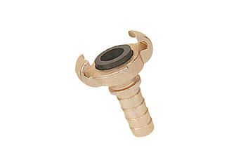
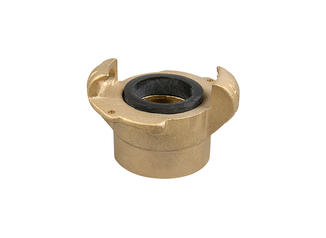
Brass
Brass camlock couplings — typically made from C360 free-machining brass — are used in applications requiring good corrosion resistance, spark resistance, and compatibility with compressed gases. Brass machines exceptionally well, which keeps manufacturing costs lower than stainless while still offering a durable, non-ferrous option. Brass is common in compressed air systems, natural gas transfer, and marine freshwater applications.
Polypropylene (PP)
Polypropylene camlock couplings are injection-molded rather than machined. PP is chemically inert to a wide range of acids and alkalis that would attack metals, making it the choice for lower-pressure chemical handling. Polypropylene camlock couplings are typically rated to 75 PSI maximum at 2-inch size, significantly below aluminum or stainless ratings. They are not suitable for elevated temperatures — PP softens above approximately 160°F (71°C).
Nylon (PA66)
Nylon camlock couplings are also injection-molded and are used in similar low-pressure chemical and agricultural applications to polypropylene. Nylon offers slightly higher impact resistance and is used where the coupling body may take mechanical abuse in the field. Its chemical resistance profile is different from PP — nylon absorbs moisture and can swell in prolonged contact with water, which is a factor to check for specific applications.
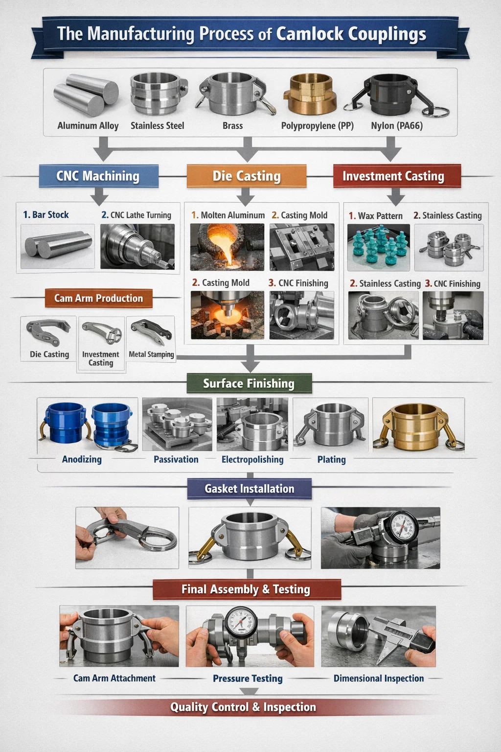
The Three Main Manufacturing Routes for Camlock Couplings
Commercial camlock coupling production uses three primary manufacturing routes. Each route produces a different quality grade, cost point, and dimensional consistency. Understanding the difference is essential for specifying or evaluating a supplier.
| Manufacturing Route | Materials Used | Dimensional Accuracy | Typical Volume | Cost Level |
|---|---|---|---|---|
| CNC Machining from Bar Stock | Aluminum, Stainless, Brass | Highest (±0.01 mm) | Low to Medium | High |
| Die Casting + Machining | Aluminum (A380) | Medium-High | High Volume | Medium |
| Investment Casting + Machining | Stainless Steel, Brass | Medium-High | Medium to High | Medium-High |
CNC Machining from Bar Stock
Bar stock machining produces the highest quality camlock couplings. A round billet of aluminum, stainless, or brass is cut to length and placed in a CNC lathe or machining center. The machine turns the outside diameter, bores the internal flow path, cuts the cam groove, machines the hose shank barbs or pipe threads, and drills any cross-holes — all in a single or two-step setup. Because the material is wrought (worked) bar stock rather than a casting, it has no porosity, more consistent grain structure, and higher mechanical strength. This route is used for stainless steel camlock couplings and for high-specification aluminum couplings where casting porosity is not acceptable.
Die Casting Followed by CNC Finishing
Die casting is the dominant production route for aluminum camlock couplings at commercial scale. Molten aluminum alloy (typically A380) is injected under high pressure into a hardened steel die. The casting solidifies in seconds and is ejected with near-net shape. The raw casting already approximates the final coupling geometry — the cam groove, body profile, and general bore are formed in the die. Post-casting CNC operations machine the critical surfaces: the cam groove diameter and depth, internal bore for flow, pipe thread if required, and hose shank barbs. Die casting allows a manufacturer to produce hundreds of coupling blanks per hour, dramatically reducing per-unit cost for standard commercial grades.
The limitation of die casting is porosity — microscopic gas pockets that form during solidification. In a well-controlled die casting process with proper die design and controlled pour temperature, porosity is minimized to acceptable levels for most camlock coupling applications. For high-pressure or vacuum service, bar stock machining is preferred because porosity in a casting can create leak paths even when the surface appears intact.
Investment Casting Followed by CNC Finishing
Investment casting (lost-wax casting) is used primarily for stainless steel camlock couplings where the geometry is too complex for economical bar machining, or where volume justifies the tooling cost. A wax pattern of the coupling is coated in ceramic slurry, hardened, and the wax burned out. Molten stainless steel is poured into the ceramic shell. The result is a near-net-shape stainless casting that requires only CNC finishing of sealing surfaces, threads, and the cam groove. Investment castings have finer grain structure than sand castings but are not as dense as bar stock. For most camlock coupling applications in stainless, investment casting plus CNC finishing is a commercially acceptable quality level.
Step-by-Step: How a Camlock Coupling Body Is Machined
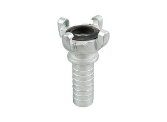
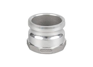
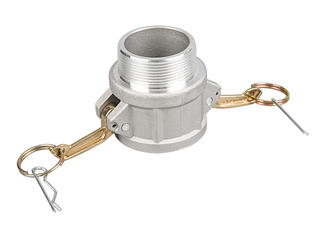
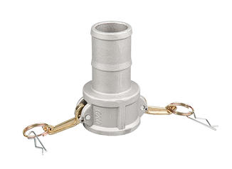
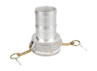
Whether starting from bar stock or a casting, the CNC machining sequence for a camlock coupling body follows a consistent set of operations. Here is the standard machining sequence for a male adapter (such as Type A or Type B) in aluminum bar stock:
- Cutoff: Round aluminum bar stock (6061-T6) is cut to blank length on a band saw or CNC bar feeder. Blank length is sized to allow for all subsequent operations with minimal waste.
- First op — OD turning and facing: The blank is chucked in a CNC lathe. The outside diameter is turned to the correct male adapter body diameter. The face is squared. The cam groove profile is turned — this is the most critical feature. The groove diameter, depth, and undercut profile must match MIL-C-27487 tolerances to ensure interoperability with any manufacturer's female coupler.
- Bore: The internal flow bore is drilled and bored to the specified inside diameter. Flow bore diameter directly affects pressure drop — undersized bores reduce flow efficiency and increase velocity-related erosion.
- Hose shank or pipe thread: If making a Type A, the hose shank end is turned and the barb profile is cut. Barb height, spacing, and outside diameter are controlled to fit the specified hose inside diameter. If making a Type B, male NPT threads are cut with a threading tool or die to ANSI/ASME B1.20.1 specification.
- Gasket groove (for female coupler types): For female coupler bodies (Type C, D, F), the internal gasket seat is machined. The gasket groove must be the correct depth and width to retain the gasket without pinching under cam-lock pressure.
- Cam arm pin holes: Two holes are drilled diametrically opposite through the coupler body wall to accept the cam arm pivot pins. Hole diameter and position must be precisely located — off-center or misaligned pin holes cause cam arms to bind, open unevenly, or fail to seal the gasket uniformly.
- Deburring: All machined edges are deburred manually or in a vibratory deburring machine. Sharp burrs on internal surfaces can score hose liners or gaskets and must be removed before assembly.
A complete camlock coupling body machining cycle on a CNC lathe with live tooling runs approximately 90 seconds to 4 minutes per part depending on size, material, and complexity. Stainless steel takes longer than aluminum due to harder material and required lower cutting speeds.
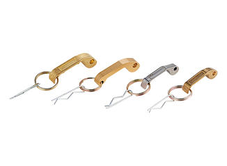
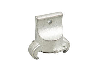
Manufacturing the Cam Arms
The cam arms are the functional locking mechanism of every camlock coupling. They are manufactured separately from the coupler body and assembled afterward. Cam arms are produced by one of three methods depending on material and volume:
Die Casting (Aluminum Cam Arms)
Most aluminum cam arms are die cast in A380 or similar alloy. The cam arm geometry — the locking lobe profile, pivot hole, and handle shape — is formed in the die. After casting, the pivot hole is reamed to final diameter for a close fit over the pin. The locking lobe surface may be lightly machined or left as-cast depending on the manufacturer's quality level. The locking lobe profile is critical: it must generate enough inward force to compress the gasket when rotated to the closed position, and must have enough geometric clearance to release cleanly when opened. A worn or incorrectly profiled lobe will either fail to seal or fail to release without excessive force.
Investment Casting or Forging (Stainless Steel Cam Arms)
Stainless steel cam arms are either investment cast or forged. Forged stainless cam arms are stronger than cast due to grain alignment from the forging process — they are specified for high-pressure or safety-critical applications. Investment cast stainless cam arms are acceptable for standard commercial service. In both cases, the pivot hole and locking lobe contact surface are CNC machined after the primary forming operation.
Stamping and Forming (Thin-Section Arms)
Some lower-cost camlock couplings use stamped and formed cam arms cut from flat sheet metal. These are less common in commercial-grade couplings but appear in budget products. Stamped arms are thinner, have less cross-section for bending loads, and the locking lobe geometry is less precise. They are recognizable by their flat, uniform thickness compared to cast or forged arms which have variable cross-section shaped for structural efficiency.
Critical Dimensions That Define Camlock Coupling Quality
The MIL-C-27487 standard specifies the key dimensions that all camlock couplings must meet for interoperability. When a manufacturer deviates from these, the coupling may not mate with other brands and may not seal reliably. The dimensions below are the most important to control in manufacturing:
| Dimension | Location | Why It Matters |
|---|---|---|
| Cam groove diameter and depth | Male adapter body | Cam arm lobe must seat fully in groove to lock and seal |
| Male adapter outer diameter | Male adapter insertion end | Must enter female coupler bore with correct clearance — too tight binds, too loose creates misalignment |
| Female coupler bore diameter | Female coupler body | Controls fit with male adapter and gasket compression |
| Cam arm pin hole spacing | Female coupler body | Controls symmetry of cam arm engagement and sealing force distribution |
| Gasket groove width and depth | Female coupler body | Gasket must be retained but not over-compressed when arms close |
| Internal flow bore diameter | Both male and female | Determines flow rate and pressure drop across the coupling |
| Cam arm lobe profile radius | Cam arm | Controls locking force and ease of operation — must follow specified cam curve |
| NPT or hose thread dimensions | Thread end | Must comply with ANSI/ASME B1.20.1 (NPT) for leak-free threaded joints |
Reputable manufacturers inspect these dimensions on every batch using go/no-go gauges for threads, digital calipers, and coordinate measuring machines (CMM) for cam groove geometry. A low-cost coupling that fails on cam groove diameter by even 0.3–0.5 mm may appear to connect but will not develop adequate gasket sealing force, resulting in leaks under pressure.
Surface Finishing Processes Applied After Machining
After machining, camlock coupling bodies and cam arms go through surface finishing operations that improve corrosion resistance, appearance, and in some cases dimensional final fit. The finishing process varies by material:
Anodizing (Aluminum)
Type II sulfuric acid anodizing is the most common finish for aluminum camlock couplings. The process grows an aluminum oxide layer approximately 5–25 microns thick on the surface, improving corrosion resistance and hardness. Anodized aluminum couplings are identifiable by their matte silver-gray or dyed color (blue, red, black finishes are common in manufacturer product lines for size identification). Type III hard anodizing (25–75 microns) is used for couplings in abrasive slurry or high-wear applications.
Passivation (Stainless Steel)
Stainless steel camlock couplings are passivated after machining by immersion in nitric or citric acid solution. This removes free iron and machining residues from the surface and promotes the formation of the chromium oxide passive layer that gives stainless steel its corrosion resistance. Passivation per ASTM A967 or AMS 2700 is the standard specification for stainless camlock couplings used in food, pharmaceutical, and chemical service.
Electropolishing (Stainless Steel)
Food-grade and pharmaceutical-grade stainless camlock couplings often receive electropolishing after passivation. Electropolishing removes a thin layer of surface metal through an electrochemical process, reducing surface roughness to Ra values below 0.8 microns. This ultra-smooth finish prevents bacteria from harboring in surface irregularities and makes the coupling easier to clean in place (CIP) or steam-in-place (SIP) sanitization cycles.
Chrome or Nickel Plating (Brass)
Brass camlock couplings may receive chrome or nickel electroplating for improved appearance and corrosion resistance in wet environments. Plating thickness is typically 5–15 microns. In potable water applications, lead-free brass alloys and NSF 61-compliant coatings are required.
Gasket Manufacture and Installation
Gaskets for camlock couplings are not machined components — they are compression-molded or cut from sheet elastomer. The gasket for a given coupling size is a simple flat ring (washer shape) in most standard designs, though some manufacturers use o-ring profile gaskets for higher-pressure applications.
Compression Molding
Elastomer compound (Buna-N, EPDM, Viton, silicone, or PTFE) is placed in a heated mold that forms the gasket shape under pressure and heat. Molded gaskets have consistent hardness (durometer), controlled dimensions, and a smooth surface that seals evenly. Camlock coupling gaskets are typically molded to 60–70 Shore A durometer — soft enough to conform under cam arm force, firm enough to resist extrusion out of the groove under pressure.
Die-Cut Flat Sheet
Lower-cost gaskets are die-cut from flat elastomer sheet. Die-cut gaskets are acceptable for standard service but may have slightly less dimensional consistency than molded gaskets. They are more common in replacement gasket kits than in OEM coupling production.
Gasket Installation in the Coupling
The gasket is pressed into the gasket groove in the female coupler body. It should sit flush or very slightly proud of the sealing face — too recessed means the gasket won't contact the male adapter face; too proud means it may not be retained in the groove during connection and could be displaced. In production, gasket installation is done manually or with simple press fixtures. The correct gasket for each coupling size is specified by the coupling manufacturer and should not be substituted with a different size or profile.
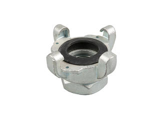
Assembly: Putting the Camlock Coupling Together
Once the machined body, cam arms, pivot pins, and gasket are ready, the coupling is assembled. Assembly for a female coupler type (such as Type C, D, or F) involves:
- Install the gasket into the gasket groove in the coupler body. Verify it is seated evenly around the full circumference.
- Position one cam arm over the pin hole on one side of the coupler body. Insert the pivot pin through the cam arm pivot hole and the body hole simultaneously.
- Repeat for the second cam arm on the opposite side.
- Secure the pivot pins — typically by peening the pin ends, pressing a retaining clip, or staking. The pin must be retained so it cannot work out during service while still allowing the cam arm to rotate freely.
- Verify both cam arms open and close smoothly without binding. In the closed position, the locking lobes should contact the coupler body groove area with no visible gap.
- Perform a functional check by inserting a male adapter of the same size and engaging the cam arms. The connection should lock firmly and release cleanly.
In high-volume production, cam arm installation is done semi-automatically with pin insertion fixtures and pneumatic staking tools. In smaller batch production or for stainless couplings, assembly is fully manual. Assembly time for a single coupling is typically 30–90 seconds for an experienced operator.
Quality Testing and Inspection for Finished Camlock Couplings
A properly manufactured camlock coupling must pass dimensional inspection and functional testing before shipment. The testing protocols used by serious manufacturers include:
Dimensional Inspection
Cam groove diameter and depth, bore diameter, thread pitch and taper, and cam arm pin hole position are checked using calibrated instruments including micrometers, calipers, thread gauges, and CMM probing. Critical dimensions are measured on a sampling basis — typically following AQL (Acceptable Quality Limit) sampling plans, with AQL 1.0 or 2.5 being common for commercial couplings. For safety-critical specifications, 100% dimensional inspection may be required.
Hydrostatic Pressure Testing
Hydrostatic proof testing involves pressurizing a connected coupling pair to 1.5× the rated working pressure, holding for a specified duration (typically 30–60 seconds), and checking for leakage or deformation. A 2-inch aluminum coupling rated at 150 PSI working pressure would be proof tested at 225 PSI. No leakage or visible deformation is acceptable at proof pressure. Burst testing — pressurizing to failure — is conducted on samples to verify the burst pressure is at least 4× the working pressure rating, establishing the safety factor.
Interoperability Testing
A manufactured female coupler should connect and seal with male adapters from at least two or three other manufacturers to verify MIL-C-27487 compliance. Interoperability failures — where a coupling will only mate with its own brand — indicate dimensional deviation from the standard and are a significant quality defect in commercial camlock couplings.
Cam Arm Retention Testing
The pivot pin retention is tested by applying a specified pull force to the cam arm and verifying the pin does not displace. Cam arm retention failure in service is a safety hazard — if a cam arm detaches under pressure, the coupling can separate with stored energy from the pressurized line. Well-manufactured couplings use staked or double-retained pins that will not release under normal operating forces.
Visual and Surface Inspection
Final visual inspection checks for burrs, surface defects, incomplete anodizing or passivation, gasket seating, and cam arm movement. Couplings destined for food-grade or pharmaceutical service receive additional inspection for surface finish Ra measurement and absence of cracks or inclusions in the sealing surfaces.
Injection Molding Process for Polypropylene and Nylon Camlock Couplings
Plastic camlock couplings follow a completely different manufacturing route from metal types. Both the body and cam arms are injection molded from polymer granules — no machining is required for the coupling body itself, though some manufacturers CNC the gasket groove and pivot holes for tighter tolerances.
Mold Design Considerations
The injection mold for a polypropylene camlock coupling body is a complex multi-cavity steel tool with internal cores that form the flow bore and cam groove. The cam groove undercut creates a challenge in mold design — the coupling cannot be ejected from a simple two-part mold without collapsing cores or side actions. Most molds use collapsible core inserts or sliding side cores that retract before ejection to release the groove undercut.
Process Parameters
Polypropylene (PP) is processed at melt temperatures of approximately 220–280°C with mold temperatures of 20–60°C. Injection pressure ranges from 800–1400 bar. Cycle time for a 2-inch PP camlock body is typically 25–45 seconds depending on wall thickness and cooling circuit design. Dimensional stability after ejection is critical — PP has a shrinkage rate of approximately 1.5–2.5%, and the mold dimensions must compensate for this to achieve the correct final coupling dimensions.
Assembly for Plastic Couplings
Plastic cam arms are also injection molded and assembled onto the coupler body using stainless steel pivot pins (using all-plastic pins is not acceptable as they lack the shear strength for service loads). The pin is pressed through both cam arm pivot holes and the coupler body, then retained by press-fit snap rings or by peening a stainless pin end. The gasket — typically EPDM or Viton — is installed the same way as in metal couplings.
What Separates a High-Quality Camlock Coupling from a Low-Quality One
The camlock coupling market includes products ranging from precision-machined, fully certified components to low-cost imports with minimal quality control. Here is what the manufacturing process differences actually mean for end users:
- Cam groove dimensional accuracy: A poorly controlled groove diameter means the cam arms do not fully engage, reducing sealing force. The coupling may appear locked but will leak at moderate pressure.
- Casting porosity: Die-cast bodies with uncontrolled porosity will seep fluid through the body wall in pressure or vacuum service even when the gasket seal is intact.
- Gasket material certification: A coupling sold for food service with an uncertified gasket material poses a contamination risk. Food-grade camlock couplings require FDA-compliant gaskets with documented traceability.
- Pin retention: Cam arms retained only by a friction-fit pin without staking or clips can walk out over repeated use cycles, eventually leading to cam arm detachment under pressure.
- Alloy specification: Budget aluminum couplings may use lower-grade alloys or recycled aluminum with inconsistent composition, reducing corrosion resistance and pressure capability compared to specified 6061-T6 or A380 alloy.
- Thread quality: NPT threads on Type B, D, E, and F couplings must comply with ANSI/ASME B1.20.1 for taper, pitch, and thread form. Undersized or over-tapered threads will cross-thread or fail to seal without excessive torque.
The price difference between a quality-controlled camlock coupling and a low-cost substitute is typically 30–80% on a per-unit basis. In most fluid transfer applications, that price gap is smaller than the cost of one field service call to address a leak or coupling failure. For chemical transfer, food service, or any application where a coupling failure causes a spill, contamination incident, or safety event, specified-quality couplings are the only acceptable choice.
Custom Camlock Coupling Manufacturing: When Standard Types Are Not Enough
Standard camlock coupling types (A through F, DC, DP) cover the majority of industrial connection requirements. However, some applications require custom configurations that are not available off the shelf. Custom camlock coupling manufacturing is available from most industrial coupling manufacturers for order quantities starting at 50–100 pieces depending on the complexity and the manufacturer.
Common custom configurations include:
- Camlock body with one end featuring a non-standard fitting — such as a flange face, sanitary tri-clamp end, or metric thread — in place of the standard hose shank or NPT thread
- Reduced-bore camlock couplings for metering or flow-restriction applications
- Extended body length couplings for insulated or jacketed pipe connections
- Camlock couplings with integral valves (ball valves or check valves) to allow dry-break disconnection
- Special material specifications — such as Hastelloy C-276 or titanium for ultra-corrosive chemical service
- Color-coded anodizing or polymer bodies for fluid identification systems in multi-product transfer facilities
Custom camlock couplings are typically produced by CNC machining from bar stock rather than casting, since the tooling cost for a custom die is not justified at the quantities usually involved. Lead times for custom camlock coupling production are generally 4–10 weeks from drawing approval depending on material availability and manufacturing load.