英语
英语 俄语
俄语Content
- 1 What Is a Pipe Coupler? A Direct Answer
- 2 Main Types of Pipe Couplers and How They Work
- 3 Materials Used in Pipe Couplers and Why They Matter
- 4 Key Specifications to Check Before Buying Any Pipe Coupler
- 5 Hose Coupling: How It Differs from a Standard Pipe Coupler
- 6 How to Install a Pipe Coupler Correctly
- 7 Where Pipe Couplers Are Used Across Industries
- 8 Common Pipe Coupler Failures and How to Diagnose Them
- 9 How to Choose the Right Pipe Coupler for Your Application
- 10 Frequently Asked Questions About Pipe Couplers
What Is a Pipe Coupler? A Direct Answer
A pipe coupler — also called a hose coupling in fluid-transfer applications — is a mechanical connector designed to join two sections of pipe, tube, or hose so that fluid, gas, or slurry can pass through the joint without leakage. The fitting seals the interface between two pipe ends and maintains structural integrity under pressure, vibration, and thermal cycling. That is the core definition; everything else about pipe couplers flows from this single function.
In practical terms, a pipe coupler can be as simple as a threaded sleeve you spin onto two pipe ends, or as sophisticated as a stainless-steel grooved coupling with an elastomeric gasket rated for 750 psi (51.7 bar) service. The variety is enormous because the demands placed on piping systems vary just as widely — a residential plumber joining PVC drain lines works with a completely different coupler than an engineer connecting hydraulic supply lines in a steel mill.
Understanding what a pipe coupler does at a fundamental level matters because choosing the wrong one is one of the most common causes of system failures. Industry surveys routinely show that improper fitting selection accounts for roughly 30–40% of fluid system leaks, which translates directly into downtime, safety incidents, and maintenance costs. The goal of this article is to give you the knowledge to make the right choice, every time.
Main Types of Pipe Couplers and How They Work
Pipe couplers are categorized by the way they grip and seal the pipe. Each joining mechanism has specific strengths, and understanding those mechanics is the fastest route to selecting correctly.
Threaded Couplers
Threaded couplers use tapered or parallel threads machined onto both the coupler body and the pipe end. Tapered threads — NPT (National Pipe Taper) in North America, BSPT in the UK and much of Asia — wedge together as you tighten them, creating a mechanical seal. Parallel threads (BSPP, metric) rely on a sealing face or O-ring rather than thread interference. Threaded connections are reliable up to about 6,000 psi in small-bore hydraulic lines and are widely used in oil and gas, plumbing, and industrial gas systems.
Compression Couplers
A compression coupler uses a ferrule — a small metal or plastic ring — that deforms radially inward when the nut is tightened, biting into the outer surface of the pipe to create a gas-tight, liquid-tight seal. No soldering or welding is needed. Compression fittings are extremely common in copper and stainless-steel tubing up to about 2 inches (50 mm) in diameter and are standard in potable water, refrigeration, and pneumatic control lines.
Grooved Couplers
Grooved (or Victaulic-style) couplers grip a circumferential groove rolled or cut near the pipe end. A key-shaped housing closes around the groove while an elastomeric gasket seals the gap between pipe ends. This design allows ±1° of angular deflection and ±3 mm of axial movement, making it ideal for fire suppression, HVAC, and process piping where thermal movement or seismic flexibility is required. Installation is several times faster than welding.
Push-Fit and Push-to-Connect Couplers
Push-fit designs rely on an internal collet ring with angled teeth that grip the pipe when it is inserted and release it only when a disconnect collar is depressed. These are most common in residential plumbing (SharkBite is the dominant brand) and in pneumatic tubing. They are fast — a connection takes roughly three seconds — but are generally limited to lower pressures, typically below 200 psi (13.8 bar) in domestic water service.
Flanged Couplers
Flanges bolt two pipe ends together with a gasket sandwiched between flat mating faces. This is the preferred method in large-diameter, high-pressure, or high-temperature piping systems — power stations, chemical plants, and refineries use flanged connections extensively. Flanges above DN 50 (2 inches) are governed by international standards such as ASME B16.5, EN 1092, or JIS B2220, which specify bolt patterns, face dimensions, and pressure ratings.
Hose Coupling Variants
A hose coupling is technically a pipe coupler adapted for flexible hose rather than rigid pipe. The most common hose coupling types are:
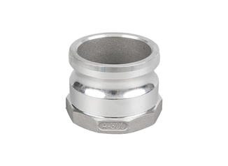
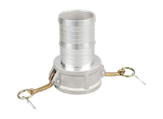
- Camlock (cam and groove): quarter-turn locking arms; widely used in agriculture, fuel transfer, and food processing
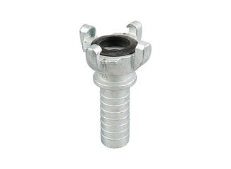
- Storz: symmetrical half-turn coupling; the international standard in fire hoses
- Crimp / swaged hose ends: a ferrule permanently swaged over the hose end; typical in high-pressure hydraulic hoses rated above 3,000 psi
- Garden-hose thread (GHT): straight, coarser threads than NPT; the residential irrigation standard in North America
The line between "pipe coupler" and "hose coupling" blurs constantly in practice; many fittings can mate rigid to flexible lines and are sold under either name depending on the industry.
| Type | Typical Max Pressure | Best For | Tool Required | Re-usable |
|---|---|---|---|---|
| Threaded (NPT) | 6,000 psi (small bore) | Gas, hydraulics, plumbing | Pipe wrench / thread tape | Yes |
| Compression | ~1,500 psi | Copper/SS tubing, refrigeration | Two wrenches | Partial (ferrule replaces) |
| Grooved | ~750 psi | Fire suppression, HVAC | Grooving tool + wrench | Yes |
| Push-fit | ~200 psi | Residential water, pneumatics | None (hand only) | Yes (with tool) |
| Flanged | 2,500+ psi (Class 1500) | Refineries, power stations | Torque wrench + gasket | Yes (new gasket) |
| Camlock Hose Coupling | ~250 psi | Agriculture, fuel transfer | None |
Yes |

Materials Used in Pipe Couplers and Why They Matter
The material of a pipe coupler is not cosmetic — it determines chemical compatibility, temperature range, corrosion resistance, and mechanical strength. A brass coupler that works flawlessly in potable water service can fail catastrophically in the same location if the fluid is changed to a chlorinated industrial solvent. The table below is a starting point, but always consult a chemical compatibility chart for your specific fluid and concentration.
Carbon Steel and Cast Iron
The workhorse of industrial piping. Carbon steel couplers handle temperatures from −29°C to +538°C and are rated for very high pressures. Galvanized versions resist moderate corrosion. Cast iron is cheaper but brittle; it is used mainly in low-pressure drain, waste, and vent (DWV) applications. Neither is suitable for salt water, seawater, or many chemicals without protective coatings.
Stainless Steel (304 and 316)
Grade 304 stainless is standard for food, beverage, and pharmaceutical applications because it resists most organic acids. Grade 316 adds molybdenum for improved resistance to chlorides and seawater. 316L (low carbon) is specified for welded assemblies where heat-affected-zone corrosion is a concern. Stainless steel hose couplings are standard in dairy plants and brewery systems.
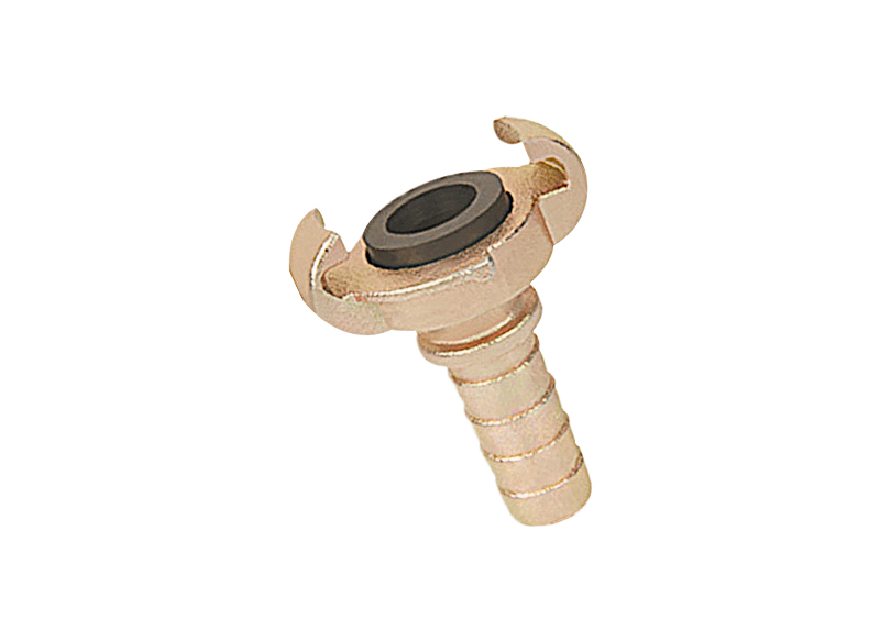
Brass and Bronze
Brass (copper-zinc alloy) offers excellent machinability, decent corrosion resistance, and a proven track record in plumbing, pneumatics, and low-pressure gas. A critical limitation: dezincification — the selective leaching of zinc — occurs in high-zinc brasses exposed to soft or acidic water. DZR (dezincification-resistant) brass addresses this. Bronze (copper-tin) is preferred in marine applications for its superior salt-water resistance.
PVC, CPVC, and PP
Thermoplastic couplers excel in corrosive chemical environments where metal options would fail. Standard PVC handles temperatures to about 60°C; CPVC extends this to roughly 93°C. Polypropylene (PP) and PVDF (polyvinylidene fluoride) are chosen for aggressive acids, alkalis, and solvents. Plastic couplers are notably lighter and lower in cost, but UV exposure and mechanical impact are their main vulnerabilities.
Key Specifications to Check Before Buying Any Pipe Coupler
Picking a coupler off a shelf without checking these parameters is how expensive leaks happen. Work through each specification systematically, even if a fitting looks like an obvious match.
- Nominal Pipe Size (NPS) or Diameter Nominal (DN)
Pipe sizing is counterintuitive: a "1-inch" pipe rarely has a 1-inch outside diameter. Under the NPS system, a 1" pipe has an OD of 33.4 mm (1.315 inches). Under DN (metric), DN 25 corresponds to NPS 1. Always verify actual OD before ordering compression or push-fit couplers, which grip on the pipe's outer surface. - Pressure and Temperature Rating
Every coupler carries a pressure rating (often listed as a WOG — Water, Oil, Gas — rating) at a reference temperature. Ratings drop at elevated temperatures. For example, a fitting rated at 1,000 psi at 21°C may derate to 500 psi at 93°C. Never exceed 80% of the rated working pressure as a practical safety margin. - Thread Standard
NPT, BSPT, BSPP, metric (DIN), JIS — these are not interchangeable even when they appear to fit. Mixing thread standards is one of the most frequent causes of cross-threading and leaks. Use a thread gauge or pitch gauge to verify before assembly. - Fluid Compatibility
Check both the coupler body material and the seal/gasket elastomer. Common elastomers include NBR (nitrile, good for oils and fuels), EPDM (good for hot water and many chemicals, incompatible with hydrocarbons), PTFE (near-universal chemical resistance), and FKM/Viton (excellent for aggressive solvents and high temperatures). - End Connections
A coupler does not have to be the same type at both ends. Reducer couplers join different pipe sizes; transition couplers (e.g., steel-to-copper or PVC-to-iron) bridge material changes; threaded-to-compression fittings bridge technology gaps. Knowing what is at each end of the joint prevents mismatches. - Certifications and Standards
Potable water couplers in the US require NSF/ANSI 61 certification. Fire protection systems require UL listing and FM approval. Pressure equipment in the EU must carry CE marking under the Pressure Equipment Directive (PED 2014/68/EU). Do not assume a cheaper coupler without marking meets the same standard as a certified one.
Hose Coupling: How It Differs from a Standard Pipe Coupler
The term hose coupling refers specifically to fittings designed to connect flexible hose to a mating connector — another hose end, a valve, a pump outlet, or a rigid pipe port. The flexibility of hose introduces demands that rigid pipe does not: the fitting must grip a soft, deformable inner liner without cutting through it, must withstand repeated bending at the joint, and must resist pull-out forces if the hose moves under pressure or vibration.
How Hose Couplings Are Assembled
There are three main assembly methods in commercial hose coupling practice:
A metal ferrule is hydraulically swaged (compressed) over the outer surface of the hose end, simultaneously gripping the hose cover and pushing the hose wire reinforcement against a barbed nipple inside. Crimp assemblies are the dominant method for high-pressure hydraulic hoses. The crimp diameter is precisely controlled — typically to within ±0.1 mm — because over-crimping can cut hose reinforcement wires, reducing burst pressure by up to 50%.
These couplings can be installed without a press, using only a vise and hand tools. A socket screws over the hose end while a stem is torqued into the bore from the inside. They are less common in hydraulics (pressure ratings are lower than crimped) but widely used in low-to-medium pressure industrial hose, garden irrigation, and dust-collection hose where field assembly speed matters.
A worm-drive or T-bolt clamp tightens around the hose over a barbed or bead-end nipple. This is the most economical method and the most common for large-diameter hoses in low-pressure applications — water discharge, air ventilation ducts, and coolant hoses. The grip depends entirely on clamp torque; under-torqueing is the most common failure mode.
Camlock Hose Couplings in Industry
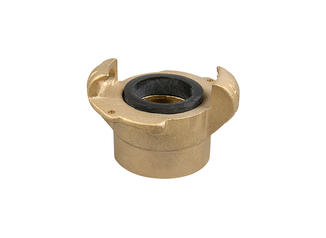
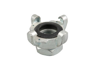
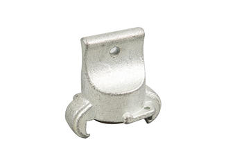
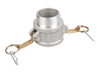
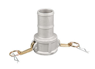
Camlock (also called cam-and-groove) is the most widely recognized quick-release hose coupling standard in North America, standardized under MIL-C-27487 and later ASME B1.20.7 and EN 14420-7. A male adapter (Part B) inserts into a female coupler (Part C) and is locked by two hinged cam arms that snap over groove pins. Connection takes under two seconds without tools.
Camlock couplings are built in six standard materials — brass, aluminum, stainless steel, polypropylene, nylon, and PVDF — and in sizes from ½ inch to 6 inches. They are the standard in agriculture (tank unloading), petroleum transfer, chemical plants, and waste-water systems. A key limitation: camlock is not self-sealing; the coupling must be locked before flow begins or the connection will pull apart under hose pressure surge.

How to Install a Pipe Coupler Correctly
Most pipe coupler failures are installation errors rather than product defects. The following guidance applies broadly across coupler types; always read the manufacturer's installation instructions for the specific fitting.
Prepare the Pipe End
Cut squarely — off-square cuts create uneven gasket loading and leak paths. Remove all burrs with a deburring tool. For compression or push-fit couplers, clean the outer surface to remove oxide, scale, and grease within 50 mm of the pipe end. Scratches running along the pipe axis can channel fluid past O-rings; keep the surface smooth.
Apply Thread Sealant Correctly
For NPT threads, apply PTFE tape (two to three wraps, starting one thread back from the end, in the thread direction) or a thread sealant compound rated for the fluid. Do not apply to the first thread — this pushes sealant into the line. For BSPP parallel threads with an O-ring or bonded seal, no thread sealant is needed; the face seal does the sealing. Applying tape to BSPP is actually counterproductive and can prevent the fitting from reaching its required torque.
Tighten to the Correct Torque
Hand-tight plus 1.5 to 2 additional turns is the correct engagement for most NPT threads in steel. Over-tightening NPT threads is a common and damaging mistake — it can crack cast fittings or split the pipe thread, creating a spiral leak path that is impossible to stop without replacement. For flanges and grooved couplers, use a torque wrench and tighten bolts in a cross pattern to the manufacturer's specification.
Pressure Test Before Full Service
Hydrostatically test at 1.5× operating pressure for a minimum of 30 minutes before insulating or burying the joint. For gas lines, a pneumatic test at operating pressure using leak-detection fluid (soapy water or commercial leak-detection spray) is standard. Never hydrostatically test with compressed air or nitrogen — if a fitting fails, the energy release is explosive rather than a manageable water leak.
Where Pipe Couplers Are Used Across Industries
The range of industries that depend on pipe couplers is wider than most people realize. Almost every manufactured product, processed food, or delivered utility involved couplers somewhere in its production chain.
High-pressure threaded and flanged couplers in wellhead equipment, production manifolds, and processing facilities. API 6A and API 6D govern most upstream couplings. Hose couplings are used extensively in tanker loading/unloading, where Storz, camlock, and dry-disconnect couplings handle volumes of hundreds of cubic meters per hour.
Quick-release hose couplings — camlock and BSP threaded — connect irrigation mainlines, chemical applicators, and slurry tankers. The annual US farm equipment market alone accounts for tens of millions of hose coupling connections. Aluminum is the preferred material for weight-sensitive mobile applications such as center-pivot irrigation.
Sanitary (tri-clamp or SMS) fittings are the pipe coupler of choice in dairy, brewery, and pharmaceutical processes because they have no threads or recesses where product can harbor bacteria. Surfaces must meet Ra ≤ 0.8 µm finish requirements under 3-A Sanitary Standards or EHEDG guidelines.
HDPE electrofusion and butt-fusion couplers join large-diameter underground water mains rated to DN 1200 and above. Grooved mechanical couplings are used in high-rise building fire suppression systems because the flexibility they allow reduces the need for costly expansion joints.
Extremely abrasive slurry and high-pressure dewatering demand rugged steel couplers, often with replaceable inner sleeves. Hose couplings in mining environments take enormous abuse — a 4-inch dewatering hose on a 500-meter run carries enough kinetic energy on water hammer to shear standard fittings.
Aircraft hydraulic systems operate at 3,000 psi standard and 5,000 psi in newer designs. MS/AN flareless and flared tube fittings to MIL-F-18866 or NAS1760 standards are the norm. Weight is critical: titanium fittings are used where every gram matters, despite their significantly higher cost compared to stainless steel.
Common Pipe Coupler Failures and How to Diagnose Them
When a pipe coupler leaks or fails, the cause is almost always one of a short list of problems. Knowing how to recognize each one saves time and prevents repeat failures.
Galvanic Corrosion at the Joint
When two dissimilar metals are coupled in the presence of an electrolyte (any conductive liquid, including condensation), galvanic corrosion eats the less noble metal. A classic example: connecting copper pipe directly to a galvanized steel coupler in a wet environment. The zinc coating on the steel corrodes aggressively. The fix is to use a dielectric union between dissimilar metals, or to ensure both the pipe and coupler are the same material or very close on the galvanic series.
Thread Galling and Seizure
Galling is a form of adhesive wear where thread surfaces cold-weld under pressure and then tear apart as the fitting is turned. It is most common with stainless steel threads because SS has a high coefficient of friction and poor natural lubricity. Always lubricate stainless threads with an anti-galling compound (nickel-based or Teflon-loaded pastes) before assembly. Once galling occurs, the fitting must be cut out and replaced — it cannot be freed without damaging the threads.
O-Ring Extrusion and Failure
An O-ring that is too small for the groove, or a groove that is too wide, allows the O-ring to extrude into the gap between coupler body and port at high pressure. This cuts the O-ring and causes an immediate leak. The cure is using the correct O-ring size (cross-section and ID both matter) and back-up rings in high-pressure applications above 1,500 psi where the clearance gap is significant.
Vibration-Induced Loosening
Pumps, compressors, and engines generate vibration that gradually backs threaded fittings out. Solutions include thread-locking compounds (Loctite 243 or similar for medium-strength retention), vibration-resistant locknuts, or switching to a mechanical coupling type — such as grooved or flanged — that does not rely on thread friction for retention. In hydraulic systems, pipe clamps spaced at intervals no greater than 1.5 m are required to prevent vibration-amplified movement at the couplers.
Water Hammer Damage
A fast-closing valve on a 150 mm water line can generate pressure spikes exceeding 10 times normal operating pressure in the first few milliseconds after closure. Rigid pipe coupler joints near the valve absorb this spike. If the fitting is not rated for transient pressure — or if the pipe is unsupported near the coupling — fatigue cracking follows. Slow-closing actuated valves, water hammer arrestors, and proper pipe anchoring are the engineering solutions.
How to Choose the Right Pipe Coupler for Your Application
A systematic selection process prevents the most common mistakes. Work through these questions in order:
- What fluid is being conveyed? Identify the chemical name, concentration, and whether it is clean or abrasive. This alone eliminates most incompatible materials.
- What is the maximum operating pressure and temperature? Note both steady-state and transient (water hammer) conditions. Design for the worst case.
- What pipe material, size, and schedule are you connecting? The coupler must be dimensionally compatible at both ends — pipe OD, wall thickness, and schedule all affect fit.
- How often will the joint be disconnected? Welded and crimped connections are permanent; flanged, grooved, and hose coupling designs support maintenance disconnection. Quick-release hose couplings (camlock, Storz) support daily cycling.
- What certifications does the installation require? NSF 61 for potable water, UL/FM for fire suppression, ATEX for explosive atmospheres — check the local regulatory requirement before specifying.
- What is the installation environment? Buried underground? Submerged? Outdoor UV exposure? High-vibration machinery? Each environment adds a constraint.
If you answer all six questions before ordering, you will narrow a field of hundreds of possible couplers down to a short list of validated options. The final choice then comes down to lead time, cost, and supplier reliability.