英语
英语 俄语
俄语Content
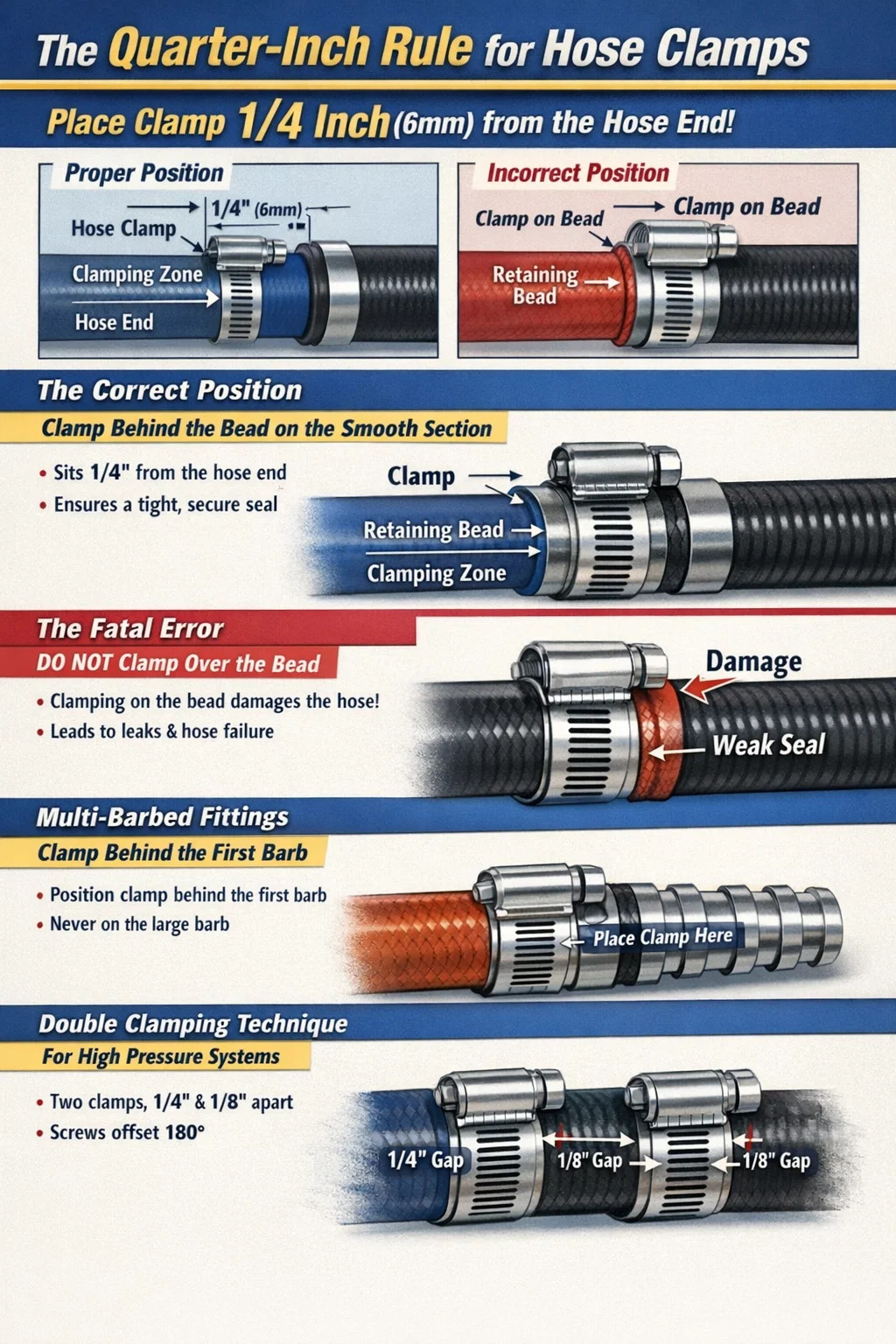
The Direct Answer: The Quarter-Inch Rule
A hose clamp must be placed exactly 1/4 inch (approximately 6 millimeters) from the cut end of the hose. Furthermore, the clamp must sit directly over the smooth, cylindrical clamping surface of the fitting, completely behind the raised retaining bead or barb.
Placing the clamp flush with the edge of the hose leaves no structural rubber to absorb the compression, causing the material to tear or extrude outward. Positioning the clamp any further than 1/4 inch up the hose often pushes the clamping band directly over the fitting's raised bead or off the fitting entirely, which severely compromises the fluid seal and mechanical grip.
Understanding Fitting Geometry for Proper Placement
To understand why placement is critical, you must evaluate the hard pipe or fitting that the hose slides onto. Standard automotive and industrial pipe connections are not perfectly straight tubes. They feature specific geometric profiles designed to interact with a properly positioned hose clamp.
The Retaining Bead
Most aluminum or plastic radiator and intercooler pipes feature a raised bump near the very end, known as the retaining bead. The sole purpose of this bead is to act as a physical wall. When you place the hose clamp directly behind this bead (on the flat side furthest from the pipe opening), the clamp creates a localized valley in the rubber. If system pressure attempts to push the hose off the pipe, the compressed rubber valley hits the rigid metal bead, stopping the hose from blowing off.
The Clamping Zone
Directly behind the bead is the clamping zone. This is a flat, smooth, cylindrical section of the pipe. Your hose clamp must sit squarely in the center of this zone. Applying radial force here guarantees 360-degree, uninterrupted contact between the inner liner of the rubber hose and the metal pipe.
The Fatal Error: Clamping Over the Bead
One of the most frequent mechanical errors in fluid system assembly is sliding the hose onto the fitting and placing the hose clamp directly over the raised retaining bead. This creates a severe structural vulnerability.
When torque is applied to a clamp positioned over the bead, the sharp inside edges of the clamp band compress the rubber directly against the hard metal ridge. Under high-vibration conditions, such as a running diesel engine or an industrial pump, this metal ridge acts like a dull knife. Internal friction causes the bead to slice through the internal nylon or Kevlar braiding of the hose. Failure analysis data indicates that over 80% of premature silicone hose ruptures are initiated by clamps placed directly on top of the fitting bead.
Additionally, placing the clamp on the bead means the band is resting on a rounded surface rather than a flat one. The clamp will invariably "walk" or slide off the bead as it is tightened, resulting in a crooked installation that applies uneven pressure and invites severe fluid leaks.
Strategies for Multi-Barbed Fittings
Brass or plastic multi-barbed fittings, commonly used in fuel lines, pneumatic systems, and irrigation, require a slightly different approach than smooth beaded pipes.
- Never place the clamp over the largest, sharpest section of a barb.
- Position the clamp over the smooth shank portion of the fitting if the manufacturer provided one behind the barbs.
- If the fitting is entirely barbed, locate the clamp directly behind the first (largest) barb near the end of the hose, ensuring it compresses the rubber into the valley between two barbs.
Compressing the hose into the valley between barbs maximizes the mechanical lock. The rubber is forced down into the grooves, creating multiple secondary sealing points that prevent low-viscosity fluids like gasoline or compressed air from escaping.
Double Clamping: Placement Rules for High Stress
In specific high-liability environments, a single hose clamp is deemed insufficient. Marine exhaust systems, heavy-duty hydraulic returns, and forced induction lines often demand double clamping. Proper placement dictates how these two clamps interact.
When installing two clamps on a single hose end, the first clamp is placed 1/4 inch from the hose edge, just as in a standard installation. The second clamp is placed immediately adjacent to the first, leaving roughly 1/8 inch of space between the metal bands. You must never allow the bands to overlap or ride up on each other, as this destroys radial uniformity.
Crucially, the screw housings (the tightening mechanisms) must be offset by 180 degrees. Every worm-gear clamp creates a slight flat spot directly underneath the screw housing where clamping force is weakest. By installing the second clamp upside down relative to the first, you place the strongest part of the second band directly over the weakest part of the first band, creating a mathematically perfect seal.
| System Pressure Profile | Recommended Quantity | Screw Orientation Offset |
|---|---|---|
| Low (0 - 30 PSI) | 1 Clamp | Not Applicable |
| Medium (31 - 60 PSI) | 1 High-Torque Clamp (T-Bolt) | Not Applicable |
| High (60+ PSI / Marine Exhaust) | 2 Clamps | 180 Degrees |
Managing Clamp Shift During Tightening
Knowing where a hose clamp should be placed is only the first step; maintaining that placement while applying torque is a separate mechanical challenge. As the threads of the worm gear engage the slots on the steel band, they exert a rotational force. This friction causes the entire clamp assembly to twist and slide forward toward the edge of the hose.
If you start tightening the clamp exactly 1/4 inch from the edge, it may drag itself flush with the hose end by the time it is fully torqued. To combat this, professionals initially position the clamp slightly deeper onto the hose (about 3/8 inch from the edge). As the nut driver applies torque, the mechanic uses their opposite hand to physically restrain the clamp housing, preventing rotational walking. The final torqued position will naturally settle precisely into the required 1/4-inch sweet spot.