 英语
 俄语

Content
- 1 Why Cam Lock Size Charts Use Nominal Pipe Size
- 2 Cam Lock Type Letters: A through F
- 3 Complete Cam Lock Size Chart with Dimensions
- 4 How to Measure a Cam Lock Fitting in Four Steps
- 5 Reducing Cam Locks and Threaded Adapters
- 6 Material Options, Size Ranges, and What Each Is Best For
- 7 Five Sizing Mistakes That Cause Leaks and Downtime
- 8 Cam Lock Size Chart FAQ
- 9 Bottom Line: Let the Chart Do the Identification Work
Suppose you are holding a camlock coupler with no part number stamped on it. The one thing you can be certain of is that the number printed on the catalog would not match the physical diameter. That is the first lesson every cam lock size chart teaches: a 2-inch cam lock measures roughly 2.5 inches in outside diameter, a 4-inch unit measures roughly 4.75 inches, and the nominal size simply refers to the hose or pipe bore it connects. The shortest path to the correct replacement is to measure the outside diameter of the fitting and compare it with a chart before ordering.
This guide explains how to read a cam lock size chart, how to identify the type letters A through F, how to measure male and female halves correctly, and how material and thread choices affect size selection. The aim is practical: get the right fitting the first time, whether you are replacing one coupler on an existing line or building a complete hose system.
Why Cam Lock Size Charts Use Nominal Pipe Size
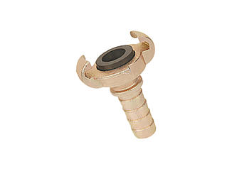
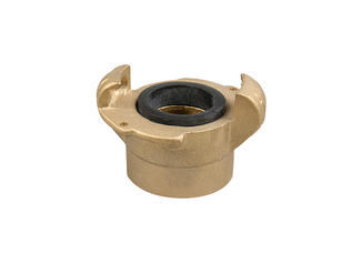
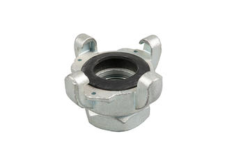
A cam and groove connection has two halves: the female coupler with two cam arms and the male adapter with a machined groove. When the spring-loaded levers are closed, the cams seat into the groove and form the seal. The size designation used by every supplier refers to the inside diameter of the hose or pipe that the fitting connects, not to the diameter of the coupling body. Cam and groove connections have been manufactured to the same interchangeability framework for decades, referenced in specifications such as MIL-C-27487 and A-A-59326, which is why a Type A from one mill usually mates with a Type C from another.
Because the body has to be thick enough to carry the cams, groove, and sealing face, the actual outside diameter runs about 0.5 to 0.75 inches larger than the nominal size. A 2-inch cam lock body comes out at roughly 2.5 inches across; a 6-inch body at roughly 6.5 inches. The relationship is consistent enough to be a useful field check, but not precise enough for ordering without a chart.
- D1 is the outside diameter of the female coupler at the grooved end.
- D2 is the outside diameter of the male adapter sleeve at the groove.
- Both are diameter measurements, never radius or thread measurements.
- Manufacturers machine within tolerance bands of roughly 0.5 to 1.0 mm, so two identical sizes can differ slightly between brands.
The practical consequence is simple: never order by nominal size alone when the old part is unmarked. Take a measurement first, then use the chart to convert that measurement into a stock size.
Cam Lock Type Letters: A through F
Every cam lock chart pairs a size with a type letter, because the same nominal size can be machined as a male adapter, a female coupler, a dust cap, or a hose shank. The letter tells you which half of the connection the part is and how it attaches to the hose or pipe.
- Type A — male adapter with hose shank; the most widely used male hose-end part.
- Type B — female coupler with hose shank; locks onto a Type A, D, or F adapter.
- Type C — female coupler with hose barb only; the most common female hose-end part.
- Type D — male plug; slides into a Type B or Type C coupler.
- Type DC — dust cap with chain; protects an unused female coupler.
- Type DP — dust plug with chain; protects an unused male adapter.
- Type E — female adapter with integrated hose shank.
- Type F — male adapter with integrated hose shank.
Choosing the correct letter matters just as much as the size. A Type A and a Type C both fit standard hose, but only when one is the male half and the other is the female half. Two Type A parts cannot lock together. The full letter-and-material matrix is covered in more depth in our guide to types and materials of camlock fittings.
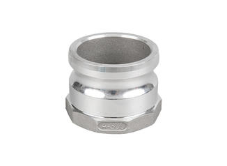
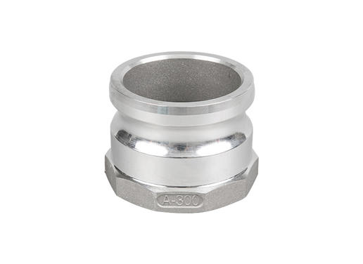 Aluminum Type A Camlock Coupling with NBR GasketThis male camlock half is suited for standard hose connections per A-A-59326 or DIN 2828. Sand-blasted aluminum keeps it light and corrosion-resistant for chemical, agricultural, and fire-fighting uses.View Product →
Complete Cam Lock Size Chart with Dimensions
The reference values below follow the widely used cam and groove dimension tables published by cpp.parts in their public camlock size chart, and they match the general sizing convention used across North American and Asian production. Actual castings can vary by up to 1.0 mm between batches, so treat the table as an identification tool rather than a precision drawing.
| Nominal Size | D1 Female OD (mm) | D2 Male OD (mm) | Approx. Actual OD | Typical Hose ID |
|---|---|---|---|---|
| 1/2 in | 23.9 | 23.4 | 0.94 in | 0.5 in |
| 3/4 in | 32.4 | 32.1 | 1.28 in | 0.75 in |
| 1 in | 37.3 | 36.7 | 1.47 in | 1 in |
| 1-1/4 in | 46.0 | 45.5 | 1.81 in | 1.25 in |
| 1-1/2 in | 54.0 | 53.5 | 2.13 in | 1.5 in |
| 2 in | 63.5 | 63.0 | 2.50 in | 2 in |
| 2-1/2 in | 76.2 | 75.7 | 3.00 in | 2.5 in |
| 3 in | 88.9 | 88.4 | 3.50 in | 3 in |
| 4 in | 114.3 | 113.8 | 4.50 in | 4 in |
| 5 in | 139.7 | 139.2 | 5.50 in | 5 in |
| 6 in | 165.1 | 164.6 | 6.50 in | 6 in |
A quick field rule from the measurement guides published by Cam Lock Direct and Proflow Dynamics: a 2-inch cam lock will measure roughly 2.5 inches in diameter, and a 4-inch coupler or adapter will measure roughly 4.75 inches. If your reading matches those ballpark figures, the nominal size is almost certainly the next lower standard inch value. Most standard production lines run from 1/2 to 6 inches; 8-inch and 10-inch sizes exist in aluminum and stainless steel but are usually made to order.
How to Measure a Cam Lock Fitting in Four Steps
You do not need the original part number. A caliper is ideal, but for sizes above 1.5 inches a standard tape measure drawn across the full width through the center is accurate enough.
- Identify the configuration. A female coupler has visible cam arms on the body; a male adapter is a smooth sleeve with a machined groove. This tells you which column of the chart to read.
- Measure the outside diameter at the grooved end. For the female coupler, take D1 across the widest machined face. For the male adapter, take D2 across the sleeve, not across the hose shank or any thread.
- Measure the bore or shank separately. The hose shank diameter must match the hose inside diameter, and threaded adapters must have their thread measured with a thread gauge. These are independent of the cam size.
- Compare D1 or D2 with the chart. If the measured value falls between two rows, verify which nominal size matches the hose ID. If it still sits between sizes, send the D1 and D2 readings to the supplier.
For threaded adapters, remember that the cam size and the thread size are two separate decisions. A 2-inch Type A can be machined with a 2-inch NPT, BSPP, or BSPT thread, and those thread standards are not interchangeable without an adapter. Measure the thread crest diameter and check the pitch before mating it with the existing pipe.
Reducing Cam Locks and Threaded Adapters
A reducing cam lock joins two different nominal sizes in a single connection, for example a 3-inch pump outlet to a 2-inch hose line. The size chart becomes two charts in this case: the female end is selected by the connection on one side, and the male end by the connection on the other. Reducing types are marked by their two sizes, and the cam arms always sit on the larger end.
- Type AA — male adapter to male adapter reduction.
- Type AR — adapter reduction with a hose shank on one side.
- Type CR — coupler reduction; female on one end, male on the other.
- Type DD and DA — double-male reductions for close-coupled installations.
- Type FR and VCR — flange-to-adapter and vertical configurations for tight spaces.
Whichever reducing type you select, apply the same measurement logic to both ends. If a reducing fitting is ordered with the wrong female or male nominal size, the connection will not seat, and field re-machining is rarely possible. A step-by-step selection process is described in our article on how to choose a camlock coupling.
 Reducing Camlock Coupling, 3/8" Male to 1/2" FemaleThis reducer joins different pipe sizes or end types, rated to 150 psi and -30 to +150°F. Its abrasion-resistant, lightweight design enables tool-free, safe transfer of fluids, powders, and pellets.View Product →
Material Options, Size Ranges, and What Each Is Best For
The material determines chemical compatibility, pressure rating, weight, and in many cases price per unit. Size availability also varies by material, because not every foundry pours the same product range in every alloy.
| Material | Common Sizes | Typical Applications | Notes |
|---|---|---|---|
| Aluminum | 1/2 to 6 in | Water, fuel, dry bulk, agriculture | Lightest metal; good corrosion resistance in neutral fluids |
| Stainless steel 304/316 | 1/2 to 6 in | Chemicals, food, pharmaceuticals, offshore | Highest corrosion resistance; costliest |
| Brass | 1/2 to 4 in | Compressed air, marine, hydraulic return lines | Good machinability; avoid ammonia and strong acids |
| Polypropylene | 1/2 to 4 in | Chemical transfer, deionized water, fertilizers | Light, low cost, good acid resistance at lower pressure |
| Nylon | 1/2 to 4 in | Abrasive powders, sandblast lines | Tough and light; less chemical resistance than polypropylene |
Pressure ratings published by suppliers for standard metal cam locks typically fall between 100 and 250 psi depending on size and alloy, with polypropylene rated at the lower end. Always compare the coupling's rating against the maximum surge pressure of the line, not the normal operating pressure.
As a manufacturer, Ningbo Chili produces cam locks in aluminum, brass, stainless steel, carbon steel, nylon, and polypropylene across the standard 1/2-inch to 6-inch range. The fastest-moving sizes in stock are usually the 1.5-, 2-, 3-, and 4-inch Type A, B, C, and E parts in aluminum and stainless steel, which makes replacement orders for those configurations quicker to dispatch.
 Stainless Steel Type C Camlock CouplingA female-threaded coupler made by investment casting, offering strength and corrosion resistance. It fits popular 1.5- to 4-inch lines and works with NPT or BSP threads for reliable quick connections.View Product →
Five Sizing Mistakes That Cause Leaks and Downtime
- Ordering by nominal size without measuring the old part. The stamped number may be worn, missing, or wrong from a previous misorder. Measure D1 or D2 first.
- Treating NPT and BSP as the same thread. BSPT has a 55-degree flank angle; NPT has 60 degrees. A pipe thread gauge resolves the difference in seconds.
- Mixing different brands without checking tolerance. Most standard-compliant couplings do mate, but castings vary; a loose or forced fit can leak under surge pressure.
- Choosing the hose shank size instead of the coupling size. The shank must match the hose ID, which in a reducing configuration can be a size or two smaller than the cam size.
- Ignoring temperature derating. Polypropylene and nylon cam locks lose structural strength above roughly 60 deg C (140 deg F). Check the material temperature curve for hot fluids.
Cam Lock Size Chart FAQ
Q: How do I know what size cam lock fitting I need?
Measure the outside diameter of the grooved end for a female coupler, or the sleeve for a male adapter, and compare the reading with the D1 or D2 column of the chart. The nominal size equals the hose or pipe bore you intend to connect.
Q: Is a 2-inch cam lock actually 2 inches in diameter?
No. A 2-inch cam lock body measures roughly 2.5 inches across the widest face. The nominal 2 inches refers to the inside diameter of the hose or pipe it connects, not the fitting body.
Q: Can I use a tape measure instead of a caliper?
For sizes of 1.5 inches and above, a tape measure drawn across the full width is accurate enough. For smaller sizes, use a caliper; a 1 to 2 mm error will move you to the wrong row of the chart.
Q: Are cam lock fittings interchangeable between brands?
In most cases, yes, when both halves are made to the same standard and tolerance band. However, castings differ between foundries. If a connection feels loose or requires excessive force to close, replace both halves from the same supplier.
Q: What is the difference between a Type C and a Type E?
Both are female hose-end parts. Type C has a hose barb only, while Type E is a female adapter with an integrated hose shank. The choice depends on how the hose end is built and which mating adapters you already own.
Q: What is the maximum working pressure for cam locks?
Published supplier ratings for metal cam locks typically range from 100 to 250 psi depending on size and material, with polypropylene units rated at or below 100 psi. Always compare the rating against the maximum surge pressure and fluid temperature of the system.
Bottom Line: Let the Chart Do the Identification Work
The cam lock size chart exists for one reason: to remove guesswork from a mechanical match that is otherwise simple. Measure D1 or D2, confirm the type letter, choose the material by chemical compatibility, and verify the thread standard before ordering. None of these steps requires a specialist.
Ningbo Chili's engineers work from the same reference dimensions, and the catalog covers the full A-to-F letter range in six materials. If a field measurement lands between two sizes, sending the D1 and D2 readings together with a photo is the fastest way to get an accurate replacement recommendation.